Quantcast
Channel: Marine Technology Archives - Marine Insight
Viewing all 277 articles
Browse latest View live

A Guide to Fire Pumps on Ship

$
0
0
main fire pump

For a seafarer, working on a ship means dealing with several challenges on a daily basis, for which, he/she needs to be prepared at all times. Fire pump on a ship is an essential machinery which helps seafarers to tackle extreme emergency situations involving fire. These marine firefighting pumps are also popularly known as Marine Fifi Pumps.

Usually, centrifugal pumps are used as marine fire pumps as they have high flow capabilities and can swiftly handle water and foam. In the event of a fire on a ship, it is very important that sufficient water is available at apt pressure, and an alternate arrangement is made in case one fire pump fails to operate or its controls are inaccessible. For this purpose, multiple marine firefighting pumps are required on board. 

Related Read: Free Sample: Centrifugal Pump Report
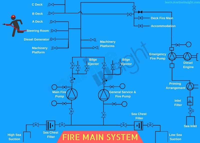
Main Fire Pumps:

The main fire pumps installed on ships are located inside the ship’s engine room, usually at the bottom platform. They are electrically driven from the main supply of the ship.

It is very common to find them installed near general service pump and ballast pumps. The general service pump lines are interconnected with the fire main and at times are used to provide water to the fire system. In some settings, they are also called general service and fire pump. These pumps should not be used for pumping oil in any case. A changeover arrangement may be provided to use the main fire pump for general service, only when it is approved by the administration.

fire pump

The general service and fire pump supply water to the following:

  1. To the fire hose connections in the engine room, main deck, accommodation, shaft tunnel, steering gear room etc.
  2. To the anchor washing at forecastle
  3. As driving water for the ejector fitted in the cargo hold bilges
  4. As driving water for the ejector fitted in the dangerous cargo hold bilges
  5. To the swimming pool, if fitted

Related Read: Brief Overview of Fire Control Plan on Ship

Capacity & Requirements for Main Fire Pumps:

The number of fire pumps and their capacity will depend on the type of ship and its gross tonnage.

For Passenger ships –

  • Passenger ships of less than 4000 GT should have at least two independent fire pumps
  • For passenger ships more than 4000GT, there should be at least three independent fire pumps installed
  • The fire pump should be capable of producing the quantity of water not less than 2/3rd of the quantity given by bilge pumps

For Cargo Ships –

  • For cargo ships of more than 1000GT, at least two fire pump should be installed with an independent driving arrangement
  • For cargo ships which are less than 1000GT, the number of fire pumps to be installed will be decided by the administration
  • The installed fire pumps should be capable of discharging a quantity of water not less than 4/3rd of the quantity given by bilge pumps in a passenger ship of the same dimension, provided that total required capacity of the pumps need not exceed  180 m³/hr in a cargo ship
  • Each main fire pump for cargo ships shall have a capacity not less than 80% of the total required capacity divided by the minimum number of required fire pumps but not less than 25 m3/hr with at least discharge of water with 2 jets

Fire Pumps

Other Important Requirements –

If the centrifugal pumps are used as a fire pump, non-return valves are fitted to prevent loss of water back through the open line when the pump is not working.

In case of positive displacement pumps used as a fire pump, a relief valve must be fitted to counter the rise in pressure if the line valve is closed and the pump is operated.

The safe line pressure will depend on the design of the fire line and capacity of the pump and it is governed by the administration.

Related Read: How High-Pressure Water Mist Fire Fighting System For Ships Works?

Emergency fire pump

On ships, every machinery is provided with a backup system i.e. one duplex or spare system or an emergency backup system. For firefighting system, the fire pump is an important machinery and if it fails the complete fire line will become inactive, leading to the spread of fire in no time. 

As per SOLAS Chapter I-2, part A regulation 4 all cargo ships of 2000 GT and above, and passenger ships of 1000 GT and above must have an emergency fire pump in a separate space other than the engine room where the main fire pumps are located.

Only in special cases, SOLAS allows the suction of the emergency pump from the same sea chest as that of the main fire pumps. This means the suction pipe must penetrate the engine room. Few classification societies allow this only if the pipings are of A-60 fire prevention standard.

The suction of the emergency fire pump can be either from a remotely operated valve or the suction valve is always kept open. The arrangement will again depend on the requirement of the classification society.

The emergency fire pump can be driven in two ways:

1  Using a diesel engine

2. Using an electrical motor supplied from the emergency generator

Fire Pumps

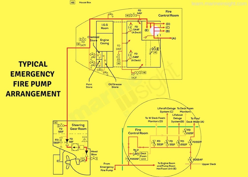
In case of fire and main fifi pump becoming non-effective (due to blackout, fire in the engine room, a problem in the main fire pump or its line etc.), the emergency fire pump is used. As the pump is located remote from the engine room space, it can be used as a backup for the main fire pump. Following locations are preferred for emergency fire pump:

  • The diesel engine marine fire pump is usually fixed on an upper deck floor of the ship, with big capacity
  • Can be fitted in the Steering flat
  • Can be fitted in the Shaft tunnel
  • Can be fitted in the Forward part of the ship (bow thruster room etc.)

Related Read: Different Types of Fire Extinguishers Used on Ships

Capacity &  Requirements

  • Emergency fire pump to be provided in Passenger ships of 1000 grt and above 
  • Emergency fire pump to be provided in cargo ships of 2000 grt and above
  • The emergency fire pump must be driven by a self-cooled compression ignition engine or by an electric motor powered from an emergency generator
  • It must be located outside the machinery space, in a compartment not forming the part of the engine room
  • The emergency fire pump must be provided with its independent suction arrangement and the total suction head should not exceed 4.5 meters under all conditions of list or trim
  • The emergency fire pump capacity to be at least 25m3/hr delivering two ½ inches bore jet of water having a horizontal throw not less than 40 ft
  • If the pump is located above the water level, a priming arrangement must be provided to fill the pump casing with water before starting
  • In a motor-driven emergency fire pump, a heating arrangement must be provided which is also supplied from the emergency switchboard power
  • For engine driven pump, the fuel tank capacity should be such that the engine can run the pump at its full load for at least 3 hrs
  • A separate reserve fuel tank to be provided outside the engine room machinery space
  • The prime mover engine should be of manual/ battery/ hydraulic start type which can be started and operated by one man

Fire Drill

Pipeline:

The pipeline used for fire pump line is usually galvanised to avoid corrosion due to seawater. The diameter of the pipe varies between 50mm to 180 mm depending upon the type and size of the ship.

Ensure not to perform any cutting or welding on the fire line as the galvanized coating will get damaged. Any major repair requires replacement of the affected portion with a spare galvanized pipe.

Operating Fire Pump:

Apart from the remote location operation, the fire pump can be operated from the following location remotely:

  • From the fire control station
  • From the engine control room
  • From the bridge
  • An arrangement can be provided in the forecastle to operate the fire pump

Related Read: A Brief Overview of Fire Control Plan on Ship

Starting the pump:

  • Check the suction valve is fully open
  • If a pump is of self-priming type (with a vacuum pump), ensure the supply tank containing the priming water is full
  • In centrifugal type fire pump, close the discharge valve and open the air vent on the volute casing
  • Close the vent once water comes out
  • Start the pump and open the discharge valve gradually
  • In the self-priming type centrifugal pump, close the check valve on the attached vacuum pump line

General Checks:

The operation of the main and emergency fire pump must be checked frequently especially during the emergency fire drills. The record of the checks made on the emergency and main fire pump must be done on Saturday or Weekly routine book. Some of the general checks include:

  • Oil and grease the bearings
  • Check the bearing temperature
  • Check the condition of gland packing
  • Check for any leakages from mechanical seal if fitted
  • When the fire pump will not be used for a longer duration (in dry docks or layups), keep the discharge and suction valve closed
  • When sailing in the cold region, keep the pump drained off the water
  • Check the standby pump when operating the other fire pump. If it is also reversing, the non-return associated with the standby pump is leaking
  • Check for abnormal noise and vibrations

Related Read: What is International Shore Connection?

Other Precautions:

  • The emergency fire pump can be installed on the bow thruster room. In case of starting the pump locally, the person needs to go down to the BT room. In case of blackout situation, the ventilation of the BT room will not work. Ensure to keep the door of the room open while entering it to start the emergency pump.
  • In freezing weather conditions, Keep the fire and deck wash water line drained
  • Never close or throttle the suction valve when the fire pump is running
  • When glad packing is used, little water leakage is considered ok. For the mechanical seal, no water leakage should be observed
  • When filling the grease, ensure to open the drain plug open which makes the old grease come out

Related Read: 16 Fire Fighting Appliances and Preventive Measures Onboard Ships

Disclaimer: The authors’ views expressed in this article do not necessarily reflect the views of Marine Insight. Data and charts, if used, in the article have been sourced from available information and have not been authenticated by any statutory authority. The author and Marine Insight do not claim it to be accurate nor accept any responsibility for the same. The views constitute only the opinions and do not constitute any guidelines or recommendation on any course of action to be followed by the reader.

The article or images cannot be reproduced, copied, shared or used in any form without the permission of the author and Marine Insight. 


An Overview Of Sludge And Bilge Management Onboard Ships

$
0
0
sludge system on ship

The operation of the main engine, various types of auxiliary machinery, and handling of fuel oil results into the production of sludge on board ships. This sludge is stored in various engine room tanks and is discharged to shore facility or incinerated onboard. Also, various leakages from seawater and freshwater pumps, leakages from coolers, etc. generates bilges.

In this article, we will see from where sludge and bilge are generated, how they are stored in engine room tanks, what record keeping is done, and how sludge and bilges are incinerated, evaporated, or discharged.

Sludge Production On Ship

Sludge on board ship comes from various sources like:

1. Fuel Oil Purifiers

The fuel oil purifiers have a designated discharge interval depending on the quality of fuel oil. After every set interval the bowl of the purifier discharges sludge accumulated, into the sludge tank or designated fuel oil purifier sludge tank. This sludge contains oily water and impurities which has been separated from the fuel oil by the purifiers.

Check our Purifier Video Course

2. Lube Oil Purifiers

The lube oil purifiers have a designated discharge interval depending on the quality of lube oil and the running hours of Main engine and Auxiliary generators. After every set interval the bowl of the purifier discharges sludge accumulated, into the sludge tank or designated lube oil purifier sludge tank. This sludge contains oily water and impurities which has been separated from the lube oil by the purifiers.

Related Read: 8 Ways To Optimize Lubricating Oil Usage On Ship

3. Main Engine Scavenge Drains

When the main engine is running, oil residue in scavenge spaces is collected from the cylinder lubrication being scrapped down from the liners. This oil is drained through scavenge drains of each unit of the main engine and collected into the sludge tank or designated scavenge drain tank.

Related Read: Everything You Ever Wanted to Know About Scavenge Fires

4. Main engine stuffing box

When the main engine is running, oil residue is collected from the stuffing box scraping oil on the piston rod. This oil comes from the stuffing box drains of each unit of the main engine is collected into the sludge tank or designated Stuffing Box drain tank.

5. Save all tray drains of oil machinery

All fuel oil machinery i.e. pumps, filters, purifiers, etc. have the tray under them to collect any leakage if occurs. The drain of the tray goes into sludge tanks.

machinery

6. Miscellaneous

They are other drains going into the sludge tank, for example, air bottle drains, fuel oil settling and service tank drains, etc. All these drains are oily water and are collected in sludge tanks.

Related Read:  A Comprehensive List of Fuel, Diesel and Lube Oil Tanks on a Ship

Sludge Tanks 

The number of sludge tanks varies from ship to ship, it depends on from which shipyard ship is built and also depends on the machinery in the engine room. Some ships have one common sludge tank and some have individual sludge tanks. Sludge pump is used to make internal transfers and transfer to shore reception facility. All sludge tanks have to be in compliance with flag state oil record book and every transfer has to be recorded in oil record book. All designated sludge tanks and bilge tanks have to be mentioned in International Oil Pollution Prevention (IOPP) certificate. Any transfer from or into IOPP tanks has to be recorded in Oil Record Book for the Engine room by the Chief Engineer.

A GUIDE TO BECOME A SUCCESSFUL MARINE ENGINEER

Sludge Incineration And Oily Water Evaporation 

The sludge generated have some water content in them coming from HFO & LO purifiers, from HFO settling and service tank drains, Air bottle drains. This water can be evaporated in the waste oil tank. Sludge is transferred from various sludge tanks into waste oil tank for incineration. Before incineration, all the water has to be evaporated so that sludge can be burned efficiently in the incinerator.

Related Read: Construction and Working of Waste Oil Incinerator

Sludge is transferred from HFO purifier sludge tank, LO purifier sludge tank and Oily bilge sludge tank into the Waste oil tank and steam valves (inlet and return) are kept open for water evaporation. The tank temperature reaches 100 degrees Celsius and water starts evaporating, when the temperature goes above 100 degrees Celsius it indicates that the water has been evaporated and oil has started to heat up. Now the sludge is ready for incineration. The quantity of water evaporated has to be recorded in the oil record book.

Sludge Line

If there is a common sludge tank, then water is allowed to settle for few days in the common sludge tank at the bottom. After the water has been settled at the bottom, suction from the bottom is taken and transferred to waste oil tank for water evaporation.

Before transferring any sludge into the waste oil tank, the temperature of the waste oil tank should be less than 90 degrees Celsius to prevent boil off in the tank. Boil off will result into instant tremendous pressure rise in the tank.

After the water has been evaporated and sludge is heated up, it is ready for incineration. For incineration, follow these steps:

  • Drain and check if any water from waste oil (sludge) in the tank before burning.
  • Agitate the sludge in waste oil tank if an agitator is present. This will help in emulsifying the oil into an even mixture for fine atomization.
  • Warm up the incinerator with diesel oil. Incinerator should be operated by a qualified person with all necessary safety precautions.
  • After warming up, open the feed valve for waste oil from the waste oil tank. Ensure steam tracing is proper for the waste oil line and strainers are not chocked. Adjust the damper and temperature according to the manual.
  • The waste oil pump will take suction from the waste oil tank. Continue burning waste oil and maintain incinerator parameters. Depending on the capacity of the waste oil pump, compare and check how much waste oil is burning in the incinerator. The final amount of sludge incinerated has to be recorded in an oil record book.

The amount of sludge generated on board is with the proportion of the fuel consumption. In general, average sludge production is considered to be 1.5% of total fuel consumption. If the sludge generation is more than 1.5%, sludge production of the ship is high.

Engine Room Bilge Water Generation

Leakages from fresh water and sea water pumps, coolers are collected in bilge wells in the engine room. Bilge wells are located at the forwarding of the bottom platform at the tank top port and starboard. Other bilge wells are at the aft of engine room, recess bilge well under the flywheel, shaft tunnel bilge well if separate space for shaft tunnel is present.

All the leakages in the engine room bottom platform are collected in these bilge wells and can be transferred to the bilge holding tank via the oily bilge pump. The oily bilge pump may also pump these spaces to the sludge tank (via the sludge pump bypass line) and the deck connections for discharge to shore or barge.

Related Read: Good Bilge Management Practices 

The oily bilge pump transfers bilges to bilge holding tank via bilge primary tank. Bilge primary tank is of smaller capacity present to separate oil from bilges. Bilge primary tank is overflowed to bilge holding tank. Any oil layer formed on top of the bilge primary tank can be removed.

The bilge tanks in the engine room are:

Bilge Holding Tank

Bilges from bilge well are transferred here and stored to be discharged overboard via oily water separator and PPM monitor or to be discharged ashore.

Bilge Primary Tank

Bilge is transferred here to separate oil by gravity. Any oil layer formed on the top can be removed

Bilge Evaporation Tank

Present on some ships in which bilge can be transferred and evaporated by heating.

Air cooler drain tank

All the moisture from Main Engine scavenge air coolers and generator scavenge air cooler is drained in this tank. They might have some oil as engine room air may contain oil vapour. Hence they are discharged overboard via PPM monitor.

bilge system on ship

Atmospheric air contains moisture and when this air is compressed in the turbocharger and then cooled in the air cooler, the moisture condenses to form water droplets. If these water droplets enter the cylinders with the scavenge air they can remove the oil film from the liner, resulting in excessive cylinder liner and piston ring wear.

Additionally, removal of water droplets from the air minimises the risk of sulphuric acid formation in the cylinders and uptakes due to the dissolving of acid products of combustion in the water droplets. In order to prevent these problems, water is removed from the combustion air by water separators fitted after the scavenge air coolers. The water droplets are directed from the air coolers, via drain traps, to the air cooler drain tank.

Related Read: Understanding Hot And Cold Corrosion In Marine Engines

This tank is pumped overboard by the air cooler drain discharge pump or bilge pump, the discharge from this pump overboard. The water flowing to the overboard discharge line passes through an oil detector, which monitors the oil content of the water being discharged overboard. It is also possible to pump the contents of the air cooler drain tank to the bilge holding tank using the oily bilge pump.

All the bilge transfers, bilge discharge overboard or to shore, bilge evaporation has to be recorded in oil record book. Whenever Oily water separator is operated, the position of the vessel at starting and stopping has to be recorded along with time and volume of bilge discharge. The PPM monitor will not allow discharge of bilge having more than 15ppm of oil content.

Related Read: How to Operate an Oily Water Separator (OWS) on Ship?

Cargo Hold Bildge Water Production

Cargo holds, generally of container vessels, have bilge wells located at the bottom on each side, port, and starboard. The hold bilges are normally pumped overboard through bilge eductor from Fire & GS pump as they contain only water. However, before pumping hold bilge wells, a visual inspection has to be carried out of the bilge wells. If any traces of oil is found, then they have to be pumped to the hold bilge collecting tank or other designated engine room tank, from where they would be processed in the OWS. Before any bilges are pumped directly overboard, it must be ensured that no local or international anti-pollution regulations will be contravened. The eductor should only be used when at sea.

The hold bilge line additionally takes suction from bow thruster room bilge wells, pipe duct bilge wells, chain locker bilge well, and forepeak void space. All the bilge wells valves can be operated remotely from the ship’s office or engine control room.

Sludge and bilge management on-board are very critical and important. MARPOL rules are very stringent and have to be followed properly to prevent pollution at sea. Any violation of MARPOL can lead to imprisonment and huge fines.

Disclaimer: The authors’ views expressed in this article do not necessarily reflect the views of Marine Insight. Data and charts, if used, in the article have been sourced from available information and have not been authenticated by any statutory authority. The author and Marine Insight do not claim it to be accurate nor accept any responsibility for the same. The views constitute only the opinions and do not constitute any guidelines or recommendation on any course of action to be followed by the reader.

The article or images cannot be reproduced, copied, shared or used in any form without the permission of the author and Marine Insight.

Sewage Treatment Plant on Ships Explained

$
0
0
sewage treatment plant

Discarding sewage produced onboard on a ship is one of the few tasks on a ship which should be taken utmost care of if one wants to save him and his shipping company from heavy fine. The sewage generated on the ship cannot be stored on the ship for a very long time and it, for this reason, it has to be discharged into the sea.

Though sewage can be discharged into the sea, we cannot discharge it directly overboard as there are some regulations regarding discharging of sewage that needs to be followed. Sewage on the sea is generally the waste produced from toilets, urinals, and WC scuppers. The rules say that the sewage can be discharged into the seawater only after it is treated and the distance of the ship is 4 nautical miles from the nearest land.

But if the sewage is not treated this can be discharged 12 nautical miles away from the nearest land. Also, the discharged sewage should not produce any visible floating solids nor should it cause any discoloration of surrounding water. The details of the sewage discharge regulations can be found in MARPOL Annex IV.

Related Read: MARPOL ANNEX 4 Explained: How to Prevent Pollution from Sewage at Sea 

Generally, ships prefer treating sewage before discharging to save themselves from any type of embarrassment. There are different methods of treating sewage available in the market, but the most common of them is the biological type for it occupies less space for holding tank, unlike those of the other methods. Moreover, the discharge generated from this plant is eco-friendly. It is to note that each sewage treatment system installed onboard has to be certified by classification society and should perform as per their requirement and regulations. 

The most preferred type of sewage treatment plant is that involving aerobic bacteria. The Anaerobic bacteria are equally capable of decomposing and breaking down the sludge but during the process, they generate and release harmful gases such as H2S and methane which are toxic and dangerous for aquatic organisms.

Related Read: 4 Important Terms Related to Sewage Treatment Plant on Ships

Component of STP:

sewage treatment plant

Screen Filter:

The screen filter mesh is fitted on the first tank near the entrance of the sewage to the STP. It helps in removing the non-sewage adulteration component such as; toilet paper, plastic paper, other solids etc, which can clog the complete system if went inside.

Biofilter:

The biofilter is also the part of the aeration chamber which treats the sewage passing from the screen filter. The biofilter reactor, with the help of fine air bubbles supplied from the blower, will disperse the contaminated substance diffusing and breaking down the organic matter by the aerobic microorganism. The fine bubble by passing through the diffuser will increase the oxygen transmission rate.  

Settling/ Sedimentation Chamber:

The treated sewage water from the biofilter reactor will come to the next chamber which is used for settling purpose. The mixture will be further separated to high-grade water and sediment after being settled in Sedimentation tank. The clarification compartment is usually of the hopper type with sloping sides which prevent the sticking and accumulating of sludge and send it to the suction side of the air lift tube.

The untreated sludge settled in the bottom of the sedimentation tank returns into the Biofilter reactor to break up by microorganism again.

Activated Carbon:

The activated carbon is fitted post the settling chamber to remove  Chemical Oxygen Demand (COD) by filtering and absorption. It also helps in treating the Biological Oxygen Demand (BOD) and Suspended Solids.

Chlorinator:

The chlorinator is fitted in the last chamber to treat the final stage water for discharging overboard. The chlorinator can be of tablet dosing type or chemical injection type. Inside the tablet-based chlorinator, clean water comes directly in contacts with the chlorine tablets, making a chlorine solution. The chlorinator comprises cylinders for filling the chlorinator with tablets.

In chemical pump type, a measured set quantity of NaOCl is injected to sterilization/chlorination tank using the diaphragm type reciprocating pump.

Sewage Treatment Plant

Related Read: Different Systems In Ship’s Accommodation Area Explained

Air Blower:

There are usually 2 air blowers installed, in which one acts as stand-by, to supply air (via air bubbles) helping in forming the microorganism in biofilter reactor. It also helps in transferring the sludge from sedimentation tank, supply air to the activated carbon tank and to back flush the sludge.

Discharge Pump:

The discharge pump is provided in a duplex and they are mounted on the last compartment of the STP. They are centrifugal pumps of the non-clog type which are coupled to their respective motors.  The pump is run on auto mode controlled by the level switches installed in the sterilization tank. The pump is usually run on manual mode when taking out the sludge from the compartments after the cleaning of the tank insides.

Piping:

  • The inlet pipe carrying the sewage to the plant is installed with the proper slope to prevent the clotting and condensation.
  • The sewage pipe is such arranged that the inside holes are accessible for cleaning during maintenance.
  • Overboard discharging outlet should be placed 200~300mm lower than L.W.L and the discharge pipe is provided with a Non-return valve.

Related Read: Pipes and Bends – An Essential Guide for Second Engineers

Floats and Level Switches:

  • Usually, Three float switches, namely – high level, low level, and high alarm level switch are fitted on the chlorination/sterilization chamber.
  • This chamber is also fitted with level switches to control the start-stop of the discharge pump.


Working of Biological Sewage Plant:

The basic principle of the working of a biological treatment plant is decomposition of the raw sewage. This process is done by aerating the sewage chamber with fresh air. The aerobic bacteria survive on this fresh air and decompose the raw sewage which can be disposed of in the sea. Air is a very important criterion in the functioning of the biological sewage plant because if air is not present, it will lead to the growth of anaerobic bacteria, which produces toxic gasses that are hazardous to health. Also, after decomposition of the sewage with anaerobic bacteria, a dark black liquid causes discolouration of water which is not accepted for discharging. Thus in a biological sewage treatment plant, the main aim is to maintain the flow of fresh air.

Division of Processes

The biological sewage plant is divided into three chambers:- 

Aeration chamber

 This chamber is fed with raw sewage which has been grounded to form small particles. The advantage of breaking sewage in small particles is that it increases the area and a high number of bacteria can attack simultaneously to decompose the sewage. The sewage is decomposed into carbon dioxide, water, and inorganic sewage. The air is forced through the diffuser into the air chamber. The pressure of air flow also plays an important role in decomposition of the sewage. If the pressure is kept high then the mixture of air and sewage will not take place properly and it will escape without doing any work required for decomposition. It is for this reason; controlled pressure is important inside the sewage treatment plant as this will help in proper mixing and decomposition by the agitation caused by air bubbles. Generally, the pressure is kept around 0.3-0.4 bars. 

Related Read: How Can Ship’s Crew Contribute towards Reducing Waste Production Onboard Ship?

Settling tank

The mixture of liquid and sludge is passed to settling tank from the aeration chamber. In the settling tank, the sludge settles at the bottom and clear liquid on the top. The sludge present at the bottom is not allowed to be kept inside the settling tank as this will lead to the growth of anaerobic bacteria and foul gasses will be produced. The sludge formed is recycled with the incoming sludge where it will mix with the later and assist in the breakdown of sewage. 

Chlorination and Collection

In this chamber, the clear liquid produced from the settling tank is overflown and the liquid is disinfected with the help of chlorine. This is done because of the presence of the e-Coli bacteria present in the liquid. To reduce these bacteria to acceptable level chlorination is done. Moreover, to reduce the e-Coli, the treated liquid is kept for a period of at least 60 minutes. In some plants, disinfection is also done with the help of ultraviolet radiation. The collected liquid is discharged to overboard or settling tank depending on the geological position of the ship. If the ship is in restricted or near coastline then the sewage will be discharged into the holding tank; otherwise, the sewage is discharged directly into the sea when a high level is reached and is disposed of automatically until low-level switch activates.

Precautions for efficient operation of STP:

  • The aeration blower is installed to run continuously as it helps the microorganism to sustain and grow. Never switch off the blower as it will cause the death of microorganisms, which will, in turn, reduce its clarification efficiency and will take days to grow microorganisms again.
  • Never throw any foreign substances such as cigarette buds, paper, rags etc. into toilets as it may choke the pipeline or filter hampering the STP operation
  • The toilet tissue used onboard should be free of vinyl components as it affects the growth of bacteria
  • Never use unauthorized chemical or detergent to clean toilet
  • The grey water inlet pipe must be placed lower than the water level of the inside of S.T.P to decrease the foam generation
  • The pH of the samples of effluent shall be in the range of 6 to 8.5
  • The Nitrite content is not to exceed 10 mg/ltr NO2.

Related Read: Maintenance and Checks for Sewage Treatment Plant on Ship

Special Area Regulation:

Currently, the Baltic Sea area is the only Special Area under Annex IV. The discharge of sewage from passenger ships within a Special Area is generally be prohibited under the new regulations, except when the ship has in operation an approved sewage treatment plant and additionally meet the nitrogen and phosphorus removal standard.

Related Read: 8 Ways in which Cruise Ships Can Cause Marine Pollution

In accordance with resolution MEPC.275(69), the discharge requirements for Special Areas in regulation 11.3 of MARPOL Annex IV for the Baltic Sea Special Area shall take effect:

1       on 1 June 2019, for new passenger ships;

2       on 1 June 2021, for existing passenger ships other than those specified in 3; and

3       on 1 June 2023, for existing passenger ships en route directly to or from a port located outside the special area and to or from a port located east of longitude 28˚10′ E within the special area that does not make any other port calls within the special area.

Marine Heavy Fuel Oil (HFO) For Ships – Properties, Challenges and Treatment Methods

$
0
0
Marine Propulsion history

The basic requirement for any marine engine is to propel a ship or to generate power onboard by using the energy obtained from burning of fuel oil. HFO or heavy fuel oil is the most widely used type of fuels for commercial vessels.

The fuel oil releases energy to rotate the ship propeller or the alternator by burning fuel inside the combustion chamber of the engine or to generate steam inside the boiler.

The amount of heat energy thus released is the specific energy of a fuel and is measured in MJ/kg.

Under MARPOL Annex 1, the definition of Heavy Grade Oil is given as:

  • Crude oils having a density at 15ºC higher than 900 kg/m3;
  • Fuel oils having either a density at 15ºC higher than 900 kg/ m3 or a kinematic viscosity at 50oC higher than 180 mm2/s; and
  • Bitumen, tar, and their emulsions

History of Marine Heavy Fuel Oil Usage

During the early 19th Century, the cargo ships, which used sails harnessing wind energy, started getting replaced by steamships.

Later on, around the second half of the 20th century, motor ships using IC engines were mainly used as commercial vessels to carry cargo.

Marine Propulsion history

The first four-stroke marine engine using heavy fuel was made operational in the 1930s. With time, shipping companies started investing more in R&D and the two-stroke engine became bigger, powerful and famous.

The use of marine heavy fuel oil became more popular in the 1950s because of the introduction of high alkaline cylinder lubrication, which was able to neutralise the acids generated by high sulphur content in the heavy fuel oil.

Related Read: Ship’s Main Engine Lubrication System Explained

In the 1960s, ships with marine engine burning heavy fuel oil became more popular and increased in number as compared to the steamships.

Eventually, in the 21st century, motor ships replaced almost all steamships and acquired 98% of the world fleet.

What Are The Properties Of Heavy Fuel Oil as per ISO 8217:2010?

Catalytic fines:

Post the refining process; mechanical catalyst particles (aluminium silicate) remain in the oil and are not easy to separate. If exceeded in number, this can damage parts of the fuel system such as an injector, fuel pumps etc. as they have very fine clearance. As per ISO 8217:2010, the maximum limit for Al+Si is 60 mg/kg for RMG and RMK category fuels.

Density:

Every matter, whether solid, liquid or gas has a specific density. The “fuel oil density” is an essential factor that indicates the ignition quality of a fuel and is also used for calculating the amount of fuel oil quantity delivered during the bunkering procedure.

Related Read: The Ultimate Guide to Fuel Oil Bunkering Process on Ships

The official and most commonly used unit for density is kg/m3 at 15°C.

Kinematic Viscosity:

Viscosity is the resistance within the fluid which acts against the flow. Kinematic viscosity represents the dynamic viscosity of a fluid per unit density. The viscosity of fuel is a highly significant parameter as it is used to determine the ease of atomization and convenience to pump the fuel within the system.

Related Read: Viscosity Meter and Viscosity Controller Used on Ships

Fuel Oil System

Typical Fuel Oil System with Heater to Reduce Viscosity

Calculated Carbon Aromaticity Index (CCAI):

The Calculated Carbon Aromaticity Index (CCAI) is a calculation based on the density and viscosity of a given fuel. As per the formula, the CCAI number is inversely proportional to efficient combustion. This means that higher the CCAI number, the more inferior the ignition quality of the fuel. CCAI helps in getting the ignition delay of the fuel and is used only for the residual fuel such as HFO. The maximum acceptable valve for HFO CCAI is 870.

Flashpoint:

The temperature at which the vapour of the heated fuel ignites is known as the fuel’s flash point. This is done under specified test conditions, using a test flame. As per SOLAS, The flashpoint for all heavy fuel oil to be used onboard vessels is set at Pensky–Martens closed- cup 60°C minimum.

Pour point:

The pour point is the temperature below which the fuel ceases to flow. Once the fuel oil temperature goes below the pour point, it forms wax which can lead to blockage of the filter. The wax formation will also build upon tank bottoms and heating coils, leading to a reduction in heat exchanging capabilities.

Sulphur:

Sulphur in the fuel is one of the main factors for sulphur oxide pollution from ships – a pollutant which is currently under major scrutiny. As per MARPOL, the current sulphur value for HFO are:

  • 3.50% m/m on and after 1 January 2012
  • 0.50% m/m on and after 1 January 2020

Related Read: A Guide To Marine Gas Oil and LSFO Used On Ships

Water content:

Water in fuel leads to a decrease in the efficiency of fuel oil and leads to energy loss. Heavy fuel oil mixed with water, if burnt, will lead to corrosion of internal parts.

Carbon residue:

A lab test of fuel can determine the carbon residue in the heavy fuel oil. The fuel tends to form carbon deposits on the surface of different parts involved in the combustion chamber under a high-temperature condition. More the amount of hydrocarbons, more difficult to burn the fuel efficiently.

Ash:

The amount of inorganic materials present in the fuel which remain as residue once the combustion process is over is called ash deposits. These deposits mainly consist of elements such as vanadium, sulphur, nickel, sodium, silicon, aluminium etc., which are already present in the fuel. The maximum limit of ash content in the fuel is 0.2% m/m.

Heavy Fuel Oil Property

Problems Of Burning HFO:

1. Water in Fuel: Water in fuel creates issues such as a decrease in heat transfer rate, loss in efficiency and wear of cylinder liner surface etc. Water can mix with fuel oil in different ways such as change of temperature leading to condensation, leaking steam pipe inside the fuel oil tank, improper storage of fuel oil (open sounding pipe) etc.

Related Read: 13 Malpractices In Bunkering Operations Seafarers Should Be Aware Of

2. Sludge formation: A ship needs to carry heavy fuel oil in abundance to ensure a continuous supply of fuel to engines and boilers during the long voyage. The heavy fuel oil is stored in the ship’s bunker tanks. Storage of such a large quantity of fuel leads to sludge formation which involves a thick layer on the bottom surface of the tanks. The sludge also sticks on the heat transfer surface of the steam pipes.

Sludge cleaning HFO tank

Cleaning HFO Tank

3. Pumpability: Many times, if the heating system of the bunker tanks fails or face a problem, it becomes difficult for the ship’s staff to pump the heavy fuel oil from bunker to settling tank due to the high viscosity of the oil. If the heavy fuel oil is of inferior quality, it will choke the filter frequently, increasing the workload of the ship staff onboard ship.

4. Mixing of different grades: Two different grades of heavy oils when mixed together in ship’s storage tanks can lead to stability problems. The number of bunker tanks on ships is limited, and when receiving fuel of different grades, it is a challenge for ship’s officer to store different grades of oils in separate tanks.

5. Combustion: The combustion of heavy fuel oil remains an issue with the ship operator as the oil need to be heated to bring the viscosity below 20cst for achieving proper atomization. If there is an issue in the heating and pumping system, the atomisation will be affected, leading to carbon deposits on the piston and liner surfaces.

6. Abrasion: The heavy fuel oil contains deposits such as vanadium, sulphur, nickel, sodium, silicon etc. which are difficult to remove and have an abrasive effect on the liner and piston surfaces.

7. Corrosion: Elements such as vanadium and sulphur, which are present in the heavy fuel oil, leads to high temperature and low-temperature corrosion respectively.

Vanadium when comes in contact with sodium and sulphur during the combustion, forms a eutectic compound with a low melting point of 530°C.

This molten compound is highly corrosive and attacks the oxide layers on the steel liner and piston (which is used to protect the steel surface), leading to corrosion.

Sulphur is also present in the heavy grade fuel. When sulphur combines with oxygen to form sulphur dioxide or sulphur trioxide, it further reacts with moisture (which can be due to low load operation) to form vapours of sulphuric acid. When the metal temperature is below the dew point of acid, the vapours condense on the surface and cause low-temperature corrosion.

Related Read: Understanding Hot And Cold Corrosion In Marine Engines

8. Lube oil contamination: During the operation, the heavy fuel oil can always enter the lubrication system and contaminate the lubricating oil. It can be due to leakage through the stuffing box, leaking fuel pumps, or unburned HFO that remains on the cylinder walls and washes down into the sump.

What Are Treatment Methods of Marine Heavy Fuel Oil Used Onboard Ship?

It is impossible to use the heavy fuel oil directly from the bunker tank without treating it. There are different methods used on a ship to treat the fuel before using it for combustion. Some of the most used methods are:

1. Heating & Draining: The fuel delivered to the ship is stored in the bunker tank where it is heated by supplying steam to the coils installed in the bunker tanks. Heating is an essential process, which makes it an integral part of fuel oil treatment. The average temperature maintained for heavy fuel oil bunker tanks is around 40ºC. After transferring it to a settling tank, the fuel is further heated to ensure it is at an appropriate temperature to enter the separators. Once the fuel is transferred to the service tank from the separator, the oil temperature is >80ºC. The main intention is to ensure the smooth pumpability of the fuel oil at different processes and to separate the maximum quantity of water from fuel by draining the settling and service tanks and using purifiers.

2. Purifiers: For removal of water and sludge from the heavy grade oil, fuel oil purifiers are used. Depending upon the owner’s choice, either conventional or modern purifiers (computer driven fuel cleaning systems) can be installed on a ship. The oil flow remains continuous even during the sludge discharge process. Purification of heavy fuel oil is considered to be the most critical treatment process and is carried out on all commercial ships.

Video Course: Understanding Ship Purifier (From Construction To Operation)

3. Filtration: Heating and purification process is used to separate water from the fuel. However, the solid impurities such as fine metal particles which can cause abrasion wear in the fuel system must also be removed. A fine filter is placed in the fuel oil supply line, which blocks the fine metal particles. These are full-flow units and the substance used inside the filters is usually natural, or synthetic fibrous woollen felt material.

Fuel Oil Duplex Filter

Fuel Oil Duplex Filter

4. Chemical treatment: Just like the automotive industry where fuel additives are popular, the maritime industry also uses chemicals in fuels for different jobs; However, this process is not much popular. The main types of residual fuel additives for marine heavy fuel oil are:
• pre-combustion additives such as demulsifiers, dispersants
• combustion improvers
• ash modifiers

Disclaimer: The authors’ views expressed in this article do not necessarily reflect the views of Marine Insight. Data and charts, if used, in the article have been sourced from available information and have not been authenticated by any statutory authority. The author and Marine Insight do not claim it to be accurate nor accept any responsibility for the same. The views constitute only the opinions and do not constitute any guidelines or recommendation on any course of action to be followed by the reader.

The article or images cannot be reproduced, copied, shared or used in any form without the permission of the author and Marine Insight.

Bow Thrusters: Construction and Working

$
0
0

Bow thrusters are a type of propeller-shaped system fitted either on the bow (forward part) and stern part (known as stern thruster) of the ship. They are smaller in size as compared to the ship’s propeller and help in better manoeuvrability of the vessel at lower speeds.

Bow thrusters are generally used for manoeuvring the ship near the coastal waters, channels or when entering or leaving a port while experiencing bad currents or adverse winds.

Bow thrusters help in assisting tugboats in berthing the ship to avoid unnecessary wastage of time and eventually money because of lesser stay of the vessel in the ports. The presence of bow thrusters on a vessel eradicates the need of two tugs while leaving and entering the port, and thus save more money. Nowadays ships have both bow and stern thruster, which makes them independent of the tugboats for manoeuvring in the port limits (if the port regulation does not make it compulsory to use tugboats).

Related Read: A Detailed Explanation of How a Ship is Manoeuvered to a Port

Installation Of Bow Thruster

Generally, side thrusters are transverse thrusters placed in a duct located at the forward and aft end of the ship. The thruster set in the forward end is known as the bow thruster and the one placed in the aft end is known as the stern thruster. The requirement for the number of thrusters to be installed depends on the length and the cargo capacity of the ship. The route of the vessel also plays an important factor as many countries have local regulations of compulsory use of tugboats to enter or leave their port limits.

Bow Thrusters

For the installation of the side thrusters, the following things are important:

  • The thruster compartment, also known as bow thruster room, should be easily accessible from the open deck by the ship’s crew
  • As most of the seagoing vessels use an electric motor for the thruster, which is a heat generating machinery and must, therefore, be positioned in a dry and well-ventilated area
  • The bow thruster room should be fitted with a high-level bilge alarm and the indication to be provided in engine control room and bridge
  • The thruster room should be well lit
  • The room should be provided with at least one light supplied from the emergency source
  • In the case of installation of more than one panel, make sure to operate the thruster from only one panel at the time
  • The thruster room should not be used to store flammable products in the area of the electric motor
  • The installation of the tunnel or conduit containing the propeller must be positioned perpendicular to the axis of the ship, in all the directions
  • The propeller should not protrude out of the conduit
  • Grid bars may or may not be fitted at both ends of the tunnel (taking into account of how much debris the ship bottom will experience in its voyage). The number of bars for them to be kept at a minimum as they tend to reduce the thrust force and overall performance of the bow thruster (or stern thruster)
  • Sharp edges on the grid bars to be avoided. Trapezoidal shape with no sharpness is a good choice of design for grid bars installed perpendicularly to the direction of the bow wave
  • The design and position of the thruster tunnel should not interfere with the water flow under hull or should not add to hull resistance
  • Ensure that the material used for the installed thruster does not foul existing equipment inside the ship such as steering links etc.

Related Read: Understanding Design Of Ship Propeller

Construction and Working of Bow Thrusters

The bow and stern thrusters are placed in the through-and-through tunnels which open at both sides of the ship. There are two such tunnels – at forward and aft ends of the ship. The thruster takes suction from one side and throws it out at the other side of the vessel, thus moving the ship in the opposite direction. This can be operated in both the directions, i.e. port to starboard and starboard to port. The bow thrusters are placed below the water line of the ship. For this reason, the bow thruster room should be checked for water accumulation at regular intervals of time.

bow thruster

Credits: Brosen/wikipedia.org

The bow and the stern thrusters can be electrically driven or hydraulic driven or diesel driven. However, the most commonly used are electric driven, as in hydraulic driven thrusters there occur many leakage problems. Also, with diesel driven bow thrusters, the amount of maintenance required is more and every time before starting someone needs to go to the thruster room to check the thrusters.

The thruster used are usually of CPP type, i.e. the blades on the propeller boss can be moved to change the direction of the thrust. The boss which carries the blades is internally provided with a movable shaft (operated by hydraulic oil) also know and Hydraulic Pod Motor driven Thrusters. Once the signal is given to change the pitch, the hydraulic oil will be supplied to operate the internal shaft (within the boss) to change the blade angle of the thruster (as shown in the video).

Related Read: 10 Precautions to Take Before Operating Controllable Pitch Propeller (CPP) on Ships

Bow thruster Parts

The motor shaft drives the shaft of the thruster via pinion gear arrangement. The sealing gasket is provided in the motor casing which holds the water which is in the tunnel.

The Thruster assembly consists of the following components:

  • The electric motor with safety relays
  • The flexible coupling between motor and thruster
  • Mounting and casing for the electric motor
  • The connecting flange and shaft
  • Motor casing seal
  • The tailpiece with shaft seal
  • Bearings
  • The propeller shaft
  • The zinc anodes
  • Grid with bars at both ends of the tunnel

Operation Of Bow Thruster:

Bow thruster consists of an electric motor which is mounted directly over the thruster using a worm gear arrangement. The motor runs at a constant speed, and whenever there is a change required in the thrust or direction, the controllable pitch blades are adjusted. These blades are moved, and the pitch is changed with the help of hydraulic oil which moves the hub on which the blades are mounted. As the thruster is of controllable pitch type, it can be run continuously, and when no thrust is required, the pitch can be made to zero.

The thruster is controlled from the bridge, and the directions are given remotely. In case of remote failure, a manual method for changing the pitch is provided in the thruster room and can be operated from there.

Related Read: How Bow Thruster is Used for Maneuvering a Ship?

Usually, the hydraulic valve block which controls the pitch of the blades is operated in the BT room for changing the blade angle in an emergency.

When the Bow Thruster is operated alone, and the signal is given to operate the pitch at port side, the thrust will result in turning the ship towards starboard side from the forward part.

Bow Thruster Operation

Similarly, when the Bow Thruster is operated alone, and the signal is given to run the pitch at starboard side, the thrust will result in turning the ship towards the port side from the forward part.

When the stern thruster and bow thruster are operated together at the same side, the ship will move laterally towards the opposite side.

As seen in the above diagrams, the bow thruster and the stern thruster provides excellent manoeuvrability to the ship.

Following things to be kept in mind when Operating the Side Thrusters:

  • Ensure to start the motor well ahead of the thruster operation and open the hydraulic lines
  • Never operate the thruster beyond its rated load else it may lead to tripping of the motor
  • Gradually increase the capacity and shift the pitch. Avoid sudden changes in the BT movement
  • The side thrusters are considered as an “on load” starting device, i.e. they should only be operated when they are submerged in water
  • Before operating the thruster, check for small craft, swimmers, boats and tugs adjacent to the thruster tunnel
  • Never touch any moving parts or the electric motor in operation
  • In the case of installation of more than one panel, ensure the thruster is operated from only one panel at a time


bow thruster of ships

Maintenance Of Bow Thrusters

1) The insulation needs to be checked regularly and should be kept dry. This is done because bow thrusters are not used frequently and thus there are chances of damages by moisture. Moreover, because of the frequent idle state of the bow thrusters, there can be a reduction in insulation resistance, especially in colder regions.

2) The space heater is checked for the working condition so that the insulation can be kept dry.

Related Read: Importance of Insulation Resistance in Marine Electrical Systems

3) The bearings of the motor and the links are to be greased every month.

4) The condition of hydraulic oil is to be checked every month for water in oil and samples should be sent for lab analysis for further checking.

5) The thickness of the contactors is to be checked from time to time.

6) Checks are to be made for any water leakages in the bow thruster room which is an indication of seal leaking.

7) The flexible coupling between the motor and thruster should also be checked.

8) Check and inspect all the cable connections for the cleanliness and tightness

9) Vacuum or blow clean the motor grid for removing the carbon grid which may increase the operating temperature

Major Maintenance Of Bow Thrusters 

The major overhauling and maintenance of the bow and stern thruster are done during the dry dock when the ship’s hull is out of the water, and the thruster blades and tunnel can be easily accessed.

Ship in Drydock

Ship in Drydock- Image Credits : S*anner 06n2ey / wikipedia

Following maintenance are usually done in the dry docking:

  • Replacement of the O’ rings and the sealing rings
  • Removal of the pinion shaft
  • Inspection and maintenance/ replacement of gear set
  • Replacement of the bearings
  • Repairs, cleaning and replacement of the blades
  • Inspection of hub and repair if needed
  • Inspection and overhauling of the oil distribution box (for operating propeller blades)

Advantages Of Using Bow Thrusters

1) Better manoeuvrability at low speeds of the ship.

2) Safety of the ship increases when berthing in bad weather.

3) Saves money due to the reduction of stay in port and less usage of tugboats.

Disadvantages Of Using Bow Thrusters

1) A very large induction motor is required, which takes a lot of current and load, and thus large generator capacity is required.

2) Initial investment is high

3) Maintenance and repairs are costly when there is damage.

The thrust force produced by the motor to move the ship will depend on various parameters such as; hull design, power source, the design of tunnel, use of grids, draft and load of the vessel etc.

The condition of the weather and state of the water also plays a vital role in BT performance.

Disclaimer: The authors’ views expressed in this article do not necessarily reflect the views of Marine Insight. Data and charts, if used, in the article have been sourced from available information and have not been authenticated by any statutory authority. The author and Marine Insight do not claim it to be accurate nor accept any responsibility for the same. The views constitute only the opinions and do not constitute any guidelines or recommendation on any course of action to be followed by the reader.

The article or images cannot be reproduced, copied, shared or used in any form without the permission of the author and Marine Insight. 

Different Types of Mechanical Measuring Tools and Gauges Used on Ships

$
0
0

Machinery onboard ships require regular care and maintenance so that their working life and efficiency can be increased, and the cost of operation, which includes unnecessary breakdowns and spares, can be reduced. For different types of machinery and systems, various measuring tools, instruments and gauges are used on a ship.

Measuring instruments and gauges are used to measure various parameters such as clearance, diameter, depth, ovality, trueness, etc. These are critical engineering parameters, which describe the condition of the working machinery.

Below, we have compiled a list of mechanical measuring instruments and mechanical gauges which are extensively used on the ship for the recording of different parameters.

Popular mechanical gauges and tools used on ships:

There are many instruments, tools and gauges which are used on a daily basis onboard ship for measurement, fault finding, wear down etc.

Following are the essential tools, gauges and mechanical instruments and their uses:

mechanical gauges

Photo by arnphoto/depositphotos

Popular mechanical gauges and tools used on ships are:

Ruler and scales

They are used to measure lengths and other geometrical parameters. This tool is one of the most famous measuring instruments in mechanical engineering. They can be a single steel plate or a flexible tape type tool. They are usually available in the measuring scale of inch or cm.

They are used for quick measurement of parts and always kept with other measuring gauge or tools in the workshop for handy access. The ruler and scales are not used where precise measurement is required. It is made from stainless steel which is durable and will not rust or corrode.

Calipers

They are usually of two types- inside and outside calliper. They are used to measure internal and external size (e.g. diameter) of an object. It requires an external scale to compare the measured value. This tool is used on those surface where a straight ruler scale cannot be used. After measuring the body/ part, the opening of the calliper mouth is kept against the ruler to measure the length or diameter.

Some callipers are integrated with a measuring scale; hence there is no need of other measuring instruments to check the measured length. Other types are odd leg and divider calliper.

mechanical gauges

Vernier Caliper

It is counted in the list of quality measuring instruments, which are used to measure small parameters with high accuracy. It has got two different jaws to measure outside and inside dimensions of an object. It can be a scale, dial or digital type Vernier calliper. Vernier calliper is one of the most used mechanical measuring tools onboard ship.

Least count of the vernier calliper is the difference between the values of main scale division and one vernier scale division.

Least Count= Value of one main scale division – Value of one vernier scale division.

= 1 mm – 9/10 mm = 1 mm – 0.9 mm = 0.1 mm or 0.01 cm

vernier caliper

Micrometer

It is an excellent precision tool which is used to measure small parameters and is much more accurate than the vernier calliper. The micrometre size can vary from small to large. The large micrometre calliper is used to measure large outside diameter or distance. E.g. Large micrometre is used as a special mechanical measuring tool for main engine to record the outer diameter of the piston rod.

They are available in two types- Inside micrometre (to measure inside diameter) and Outside micrometre (for measuring outside diameter).

The Least count of the micrometre is 0.01 mm or 0.001cm.

Micrometer

Source: Wikimedia/Lucasbosch

Feeler gauge

Feelers gauges are a bunch of fine thickened steel strips of different thickness bundled together. The thickness of each strip is marked on the surface of the strip. The feeler gauge is used to measure the clearance or gap width between surface and bearings.

E.g. The feeler gauge is widely used to measure piston ring clearance, engine bearing cleaner, tappet clearance etc.

feeler gauge

Source: Wikimedia/Qurren

Telescopic Feeler Gauge

Similar to the functionality of feeler gauge, this type of gauge is also known as tongue gauge, and it consists of long feeler gauge inside a cover with tongue or curved edge.

The long feeler strips protrude out of the cover like a telescope so that it can be inserted into remote places where feeler gauge access is not possible. E.g. It is used to measure the bearing clearance of the top shell.

It is essential that after the use of the telescope gauge, the strip should be cleaned and retracted back to its housing, else it may damage the feeler strip.

telescopic tongue gauge

Poker Gauge

Poker gauge is one unique tool among different types of measuring instruments is available in mechanical or digital form on ships.  It is only used for one purpose; To measure propeller stern shaft clearance, also known as propeller wear down. It is a type of depth measuring instrument, whose reading indicates the wear down of the stern shaft.

A special access point or plate is provided which can be either open, bolted, secured or welded, depending upon the ship design. The Poker gauge is inserted to in this access point to measure the propeller drop. The poker gauge is a special instrument which is kept with the chief engineer, and the reading is usually taken every dry dock.

The design of the poker gauge may vary as each vessel has customised poker gauge made available during the handing over from the shipyard. While taking the reading the shaft to be turned, so that propeller boss matches with the marking of the shaft.

Bridge Gauge

As the name suggests, Bridge gauge looks like bridge carrying the measuring instrument at the centre of the bridge. They are used to measure the amount of wear of Main engine bearing. Typically the upper bearing keep is removed, and clearance is measured for the journal. A feeler gauge or depth gauge can be used to complete the process.

Bridge Gauge

A feeler gauge or depth gauge can be used to complete the process.

Liner Measurement Tool

A liner measurement tool is a special tool for marine engines which comes in a set of the straight rod of different marked length, which can be assembled together to make the measuring tool of the required length. It is used to measure the wear down or increase the diameter of the engine liner.

It is considered as special tools when compared to other types of measuring tools and kept separately with other engine special tools under chief engineer or 2nd engineer supervision.

liner measurement tool

American Wire Gauge

American wire gauge or AWG is a standard tool which is circular and has various slots of different diameter in its circumference. It is used to measure the cross section of an electric cable or wire. This tool is usually kept in the electrical workshop of the ship, and electrical officer uses it for measuring wire thickness.

Wire Gauge - AWG

Source: Wikimedia


Bore Gauge

A tool to accurately measure the diameter of any hole is known as bore gauge, It can be a scale, dial or digital type instrument. The most common type which is used on the ship is dial type bore gauge, which comes with a dial gauge which is attached to the shaft and replacement rods, also known as measuring sleds, of different size to measure different hole dimensions.  It is usually calibrated in 0.001 inch (0.0025 cm) or 0.0001 inch (0.00025 cm).

Bore Gauge

Source: Wikimedia

Depth Gauge

A depth gauge is used to measure the depth of a slot, hole or any other surface of an object. It can be of scale, dial or digital type. The depth gauge can be a micrometre style type, a dial indicator type, or modified Vernier type tool, which means the measuring base is fitted on the reading scale of a micrometre, dial indicator or the Vernier scale.

Angle Plate or Tool

As the name suggests, this is a tool comprising of two flat plates which are at a right angle to each other, and it is used to measure the exact right angle of an object or two objects joined together. This tool is usually kept in workshop away from any tools or chemical which may roughen the surface of the angle plate.

Angle plate

Source:wikimedia

Flat Plate

The flat plate or a surface plate is a precision flat surface used to measure the flatness of an object when it is kept over the flat plate acting as a reference. The flat plate is also kept in a workshop in a secure location, and a wooden piece is usually held on the top of the flat surface as the protective cover to safeguard the surface. Regular visual inspection and calibration need to be done to check for wear, scoring etc. on the surface.

Flat/ Surface plate

Dial Gauge

The dial gauge is utilised in different tools as stated above and can be separately used to measure the trueness of the circular object, jumping off an object, etc. It consists of an indicator with the dial, which is connected to the plunger carrying the contact point. Once the contact point is kept in touch with an object (to be measured), any unevenness or jumping will cause the plunger to move.

The plunger is connected to the pointed in the dial. The dial is such attached that it does not retract but swings in an arc around its hinge point to show the reading in the indicator.

Dial Gauge

Source: Wikimedia/Solaris2006

Lead Wire

It is a conventional method to use soft lead wire or lead balls to measure the wear down or clearance between two mating surfaces. The lead wire or balls of fixed dimension (which is usually larger than the expected clearance) are kept between two surfaces, and both are tightened against each just as in normal condition. The change in the width of the lead wire or ball will show the clearance or wear down.

 Oil Gauging Tapes

Also known as sounding tapes, these are special types of gauges only used to measure the level of the fluid (HFO, DO, Lubes, Water etc.) inside the ship’s tanks. The sounding tapes can be of a mechanical type where the tape is retracted in a coil and connected to a heavy bob at the end. The mechanical tapes are the most commonly used in all dry ships, however, in tankers ships, electronic sounding gauges, electrically powered servo type gauges, ultrasonic type etc.

taking tank sounding

Credits: US Navy/Wikipedia.org


Seawater Hydrometer

A small glass instrument for measuring the density and saturation of the salt in the seawater. This is an essential tool for deck officers as the draft survey will be determined using the water density to calculate the cargo weight for loading. It is also used for ensuring compliance with the load line survey.

Crankshaft Deflection Gauge

A form of dial gauge specifically made to measure the crankshaft deflection of the marine engine. The working is similar as explained in the dial gauge, the only difference is the construction which let this tool hang between two webs allowing it to measure the deflection when the crankshaft rotates.

Crankshaft deflection

Engine Peak Indicator

A measuring instrument for a marine engine with pressure indicator dial used to measure the peak pressure generated inside the engine cylinder. The pressure indicator dial is connected to the blowdown valve located on the top of the cylinder. There is a check valve provided before the indicator, which when opens will the pressurised gases to continually flow inside the indicator till it reaches the maximum value in the dial.

Once the pressure is measured, an exhaust valve provided on the side of the valve is opened which release the pressurised gas from the instrument. It is an oil filled pressure gauge instrument which helps in resisting the vibration and also acts as good heat resistant.

Engine Indicator Diagram Tool

It is a cylindrical device containing the indicator piston with spring and needle, used to draw the indicator diagram for a particular cylinder when it is fixed on the indicator cock of the unit.

The internal pressure changes in the cylinder are transferred to the indicator piston which is balanced with the spring. The displacement in the piston is magnified and transformed into an indicator diagram by using a precision link mechanism connected to a metal stylus.

Planimeter

An instrument which is used to measure areas of irregularly shaped areas of an arbitrary two-dimensional shape on plans or drawings.

planimeter

Source: Wikimedia/Stefan Kühn

These are some of the primary tools and gauges types that are used on board ship. If you feel we have missed any vital tool, then let us know, and we will add it to the list.

Disclaimer: The authors’ views expressed in this article do not necessarily reflect the views of Marine Insight. Data and charts, if used, in the article have been sourced from available information and have not been authenticated by any statutory authority. The author and Marine Insight do not claim it to be accurate nor accept any responsibility for the same. The views constitute only the opinions and do not constitute any guidelines or recommendation on any course of action to be followed by the reader.

The article or images cannot be reproduced, copied, shared or used in any form without the permission of the author and Marine Insight. 

SaveSaveSaveSave

SaveSaveSaveSaveSaveSaveSaveSave

SaveSaveSaveSaveSaveSave

SaveSaveSaveSave

A Guide To Scrubber System On Ship

$
0
0
Packed Bed Scrubber

Scrubbers or Exhaust Gas Cleaning Systems (EGCS) are used to remove particulate matter and harmful components, such as sulphur oxides (SOx) and nitrogen oxides (NOx) from the exhaust gasses generated as a result of combustion processes in marine engines, to implement pollution control.

These scrubbing systems have been developed and employed to treat exhaust from engines, auxiliary engines and boilers, onshore and onboard marine vessels, to ensure that no damage is done to human life and the environment by toxic chemicals.

Sulphur emissions to the atmosphere by sea-going vessels are limited by new and updated international regulations, which will come into effect starting 01 January 2020 under the Marpol Treaty.

Related Read: 10 Technologies/Methods for Controlling NOx & SOx Emissions from Ships

The International Maritime Organization (IMO) regulations mandate that the sulphur content in fuels, which is carried by merchant vessels, has to be limited to 0.50% globally and 0.10 % m/m in ECAs (Emission Control Areas; The Baltic Sea Area, The North Sea area, The United States, Canada, and the United States Caribbean Sea area).

Before this, the maximum sulphur cap in fuels has been kept at 3.5% m/m. Compliance with the new regulations requires that vessels either use expensive fuel with low sulphur content or clean the exhaust gases by using exhaust scrubbing systems.

Exhaust gas scrubbers are hence being installed on a substantial number of ships to comply with international regulations and standards economically.

Related Read: Download FREE eBook – A Guide to ECA Compliance For Ships + 4 Bonuses

Operational Principle of Scrubber System

Exhaust gas streams are passed inside the scrubber where an alkaline scrubbing material is present to neutralize the acidic nature of the exhaust gasses and remove any particulate matter from the exhaust.

The used-up scrubbing material is then collected with wash water which may be stored or disposed of immediately as the effluent. The cleaned exhaust is passed out of the system and into the atmosphere. The scrubbing material is chosen such that specific impurities like SOx or NOx can be removed by suitable chemical reactions.

Related Read: Understanding Various Components of Exhaust Gas Emissions from Ships

For de-sulphurization purposes, marine scrubbers use lime or caustic soda such that sulphur-based salts are produced after treatment, which can be easily discharged as they do not pose a threat to the environment. Scrubbers may use sea water, fresh water with added calcium/sodium sorbents or pellets of hydrated lime as the scrubbing medium because of their alkaline nature.

To increase the contact time between the scrubbing material and gas, packed beds consisting of gas-pollutant removal reagents (such as limestone), are used inside the scrubbers. These packed beds they slow down the vertical flow of water inside the scrubbers and intensify the exhaust gas cooling and acidic water neutralization process. Scrubbers are designed to maximize the absorption of gasses passing through it. 

Classification of Marine Scrubbers

On the basis of their operation, marine scrubbers can be classified into Wet and Dry scrubbers. Dry scrubbers employ solid lime as the alkaline scrubbing material which removes sulphur dioxide from exhaust gasses. Wet scrubbers use water which is sprayed into the exhaust gas for the same purpose.

Related Read: 8 Ways to Achieve Efficient Combustion in Marine Engines

Wet scrubbers are further classified into closed-loop or open loop scrubbers. In close looped scrubbers, fresh water or sea water can be used as the scrubbing liquid. When Fresh water is used in closed loop scrubbers, the quality of water surrounding the ship has no effect on the performance and the effluent emissions of the scrubber. Open-loop scrubbers consume sea water in the scrubbing process.

Types of scrubbers

Hybrid scrubbers can utilise both closed and open running modes either at the same time or by switching between the two. Seawater hybrid scrubbers can be operated both in closed or open mode with seawater used as the scrubbing medium.

Wet Scrubbers 

Inside a wet scrubber, the scrubbing liquid used may be sea water or fresh water with chemical additives. The most commonly used additives used are caustic soda (NaOH) and Limestone (CaCO3). Scrubbing liquid is sprayed into the exhaust gas stream through nozzles to distribute it effectively. In most scrubbers the design is such that the scrubbing liquid moves downstream, however, scrubbers with an upstream movement of scrubbing liquids are available as well.   

Wet Scrubber Venturi Type

Figure 2.1


The exhaust inlet of the scrubber can be made in the form of a venturi, as shown in Figure 2.1, in which the gas enters at the top and water is sprayed in the high exhaust gas speed areas at the neck or above the neck in the form of a spray. An inline scrubber is shown in figure 2.2.

The exhaust intake is either on the side or the bottom of the tower. The designs ensure that the sulphur oxides present in the exhaust are passed through the scrubbing liquid; reacting with it to form sulphuric acid. When diluted with alkaline seawater, sulphuric acid which is highly corrosive in nature can be neutralised.

Related Read: 10 Technologies/Methods for Controlling NOx & SOx Emissions from Ships

The wash water is discharged into the open sea after being treated in a separator to remove any sludge from it and the cleaned exhaust passes out of the system. Mist eliminators are used in scrubbing towers to remove any acid mist that forms in the chamber by separating droplets that are present in the inlet gas from the outlet gas stream.

Packed Bed Scrubber

Figure 2.2


MARPOL regulations require that the wash water used has to be monitored before being discharged to ensure that its PH value is not too low. Since the alkalinity of seawater varies due to the number of reasons such as the distance from land, volcanic activity, marine life present in it etc, wet scrubbers are divided into two types; open loop and closed loop systems. Both these systems have been combined into a hybrid system, which can employ the most suitable scrubbing action depending upon the conditions of the voyage.

Open Loop Scrubber System 

This system uses seawater as the scrubbing and neutralising medium, no other chemicals are required for desulphurization of gasses. The exhaust stream from the engine or boiler passes into the scrubber and is treated with only alkaline seawater only. The volume of this seawater depends upon the size of the engine and its power output.

Related Read: Understanding Components and Design of Exhaust Gas System of Main Engine On Ship

The system is extremely effective but requires large pumping capacity as the amount of seawater required is quite high. An open loop system works perfectly satisfactorily when the seawater used for scrubbing has sufficient alkalinity. However, sea water which is at high ambient temperature, fresh water and even brackish water, is not effective and cannot be used. An open loop scrubber for these reasons is not considered as a suitable technology for areas such as the Baltic where salinity levels are not high. 

Open Loop Scrubber System
Reactions Involved:

SO2 (gas) + H2O + ½O2 → SO4 2- + 2H+ (Sulphate ion + Hydrogen ion)
HCO3 + H+ → CO2 + H2O (Carbon-di-oxide + Water)

Advantages:

1. It has very few moving parts, the design is simple and easy to install on board.
2. Apart from de-fouling and operational checks, the system requires very less maintenance
3. This system does not require storage for waste materials

Disadvantages:

  1. Cooling of the exhaust gas is a problem faced by wet scrubber systems.
    2. The operation of the system depends upon the alkalinity of water available and is not suitable to 3. be employed in all conditions.  
    4. A very large volume of sea water is required to obtain efficient cleaning and hence the system consumes very high power.  
    5. In ECA zones and ports, higher costing fuel has to be consumed.

Closed Loop Scrubber System 

It works on similar principals to an open loop system; it uses fresh water treated with a chemical (usually sodium hydroxide) instead of seawater as the scrubbing media. The SOx from the exhaust gas stream is converted into harmless sodium sulphate. Before being re-circulated for use, the wash water from a closed loop scrubber system is passed through a process tank where it is cleaned.

The process tank is also needed for the operation of a circulation pump that prevents pump suction pressure from sinking too low.

Ships can either carry fresh water in tanks or generate the required water from freshwater generators present on board. Small amounts of wash water are removed at regular intervals to holding tanks where fresh water can be added to avoid the build-up of sodium sulphate in the system.

A closed-loop system requires almost half the volume of wash water than that of the open loop version, however, more tanks are required. These include a process tank or buffer tank, a holding tank through which discharge to sea is prohibited and also a storage tank capable of regulating its temperature between 20º and 50ºC for the sodium hydroxide which is usually used as a 50% aqueous solution  

Closed Loop Scrubber System

Dry sodium hydroxide also requires large storage space. The hybrid system is a combination of both wet types that can operate as an open loop system when water conditions and the discharge regulations allow and as a closed loop system at other times. Hybrid systems are hence proving to be the most popular because of their ability to cope with different conditions.

Reactions Involved

2NaOH + SO2 → Na2SO3 + H2O (Sodium Sulphite);
Na2SO3 +SO2 +H2O → 2NaHSO3 (Sodium Hydrogen Sulphite);
SO2 (gas) + H2O + ½O2 → SO42-  +  2H+ ;
NaOH + H2SO4 → NaHSO4 + H2O (Sodium Hydrogen Sulphate);
2NaOH + H2SO4 → Na2SO4 + 2H2O (Sodium Sulphate).

Advantages:

1. Very less maintenance is required.
2. It is independent of the operating environment of the vessel.
3. Cooling of exhaust gas is a problem with wet scrubbing systems.

Disadvantages

  1. It requires storage space (buffer tank) to hold waste water until it can be discharged
    2. Selective catalytic reduction systems must operate before wet scrubbers.
  2. Fitting the system together, especially for dual-fuel engines can be quite complex.

Hybrid Scrubber System

These systems offer a simple solution for retrofitting vessels with scrubbers that are capable of operation on both open loop and closed loop configurations. These systems run on open loop mode at sea and closed loop mode in ECA zones and ports and their use can be switched with ease. As the system can run on lower costing fuels for longer periods of time and around the world, they can overcome their high initial costs in order to economically meet with the international regulations.

Related Read: Marine Heavy Fuel Oil (HFO) For Ships – Properties, Challenges, and Treatment Methods

Hybrid Scrubber system

Advantages:

  1. Suitable for long and short voyages around the world
  2. Ships with Hybrid scrubbing systems can spend more time in ECA zones and on port than those with open loop systems
    3. Can use lower costing HFO (Heavy Fuel Oil) all of the time.

Disadvantages

1. More structural modifications are needed to employ this system.
2. Requires large storage space for chemicals and additives.
3. The system has a high installation time and cost.

Dry Scrubbers

In these types of scrubbers, water is not used as a scrubbing material, instead, pellets of hydrated lime are used to remove sulphur.

The scrubbers are at a high temperature than their wet counterparts and this has a benefit that the scrubber burns off any soot and oily residues in the system. The calcium present in caustic lime granulates reacts with the sulphur dioxide in the exhaust gas to form calcium sulphite.

Calcium sulphite is then air-oxidized to form calcium sulphate dehydrate, which with water forms gypsum.  The used pellets are stored on board for discharge at ports, however, they are not considered a waste as the gypsum formed can be used as a fertiliser and as construction material.

Dry scrubber systems consume less power than wet systems as they do not require circulation pumps. However, they weigh much more than wet systems.

Reactions Involved

SO2 + Ca(OH)2 → CaSO3 + H2O (Calcium Sulphite)
CaSO3 + ½O2 → CaSO4  (Calcium Sulphate)
SO3 + Ca(OH)2 → CaSO4 + H2O (Gysum)


Advantages

1. There is efficient removal of nitrogen and sulphur oxides
2. This type of system does not result in the production of liquid effluent that must be disposed of overboard.
3. The Gypsum obtained after the exhaust gas cleaning process can be sold for use in various industrial applications

Disadvantages

They require significant onboard storage to handle the dry bulk reactants and products associated with the process.
There must be a readily available supply of the reactants.
the reactants used are costly, especially urea for NOx abatement and calcium hydroxide for SOx abatement

Related Read: 14 Technologies to Make the Ultimate Green Ship

Choice of Scrubber System

In order for a shipping company to select the most suitable kind of scrubber system to be installed on board, there are many factors it must consider. These include; the installation spaces available on board, the area of operation and the chartering schedule of the ship, the power and output of the engine and boiler on board, the availability of fresh water on board and the available power on board to run the system in different conditions, amongst others.

Disclaimer: The authors’ views expressed in this article do not necessarily reflect the views of Marine Insight. Data and charts, if used, in the article have been sourced from available information and have not been authenticated by any statutory authority. The author and Marine Insight do not claim it to be accurate nor accept any responsibility for the same. The views constitute only the opinions and do not constitute any guidelines or recommendation on any course of action to be followed by the reader.

The article or images cannot be reproduced, copied, shared or used in any form without the permission of the author and Marine Insight. 


Types of Governors for Engines Used On Ships

$
0
0
Flyweights of Governor

A governor is a system that is used to maintain the mean speed of an engine, within certain limits, under fluctuating load conditions. It does this by regulating and controlling the amount of fuel supplied to the engine. The governor hence limits the speed of the engine when it is running at the no-load condition, i.e it governs the idle speed, and ensures that the engine speed does not exceed the maximum value as specified by the manufacturers.

All marine vessels need a speed control system to control and govern the speed of the propulsion plant being used on board, as there can be a large number of variations that arise on engine load, which may damage the engine and cause loss of life and equipment. The variations in the load on the engine may arise due to several factors such as rough seas, rolling and pitching of the vessel, compromised ship structure, changes in weight of the ship among others.

Governors are also fitted in auxiliary diesel engines or generators, and alternators on the ship.

Related Read: Over Speed Trip in Diesel Engines & Types of Over Speed Trips


Classification of Governors on the basis of Design and Construction 

Mechanical Governors


These governors consist of weighted balls, or flyweights, that experience a centrifugal force when rotated by the action of the engine crankshaft. This centrifugal force acts as the controlling force and is used to regulate the fuel supplied to the engine via a throttling mechanism connected directly to the injection racks. These weight assemblies are small and hence the force generated is not enough to control the injection pumps of large engines. They can be used where exact speed control is not required. They have a large deadband and have small power output.

Related Read: Fuel Oil Consumption Calculations For Ships: What Seafarers Should Know

Advantages of mechanical governors

1. They are cheap.
2. They can be used when it is not necessary to maintain an exact speed depending on the load.
3. They are simple in construction and have only a few parts.

Mechanical Governor

Hydraulic governors

In hydraulic governors, the weighted assembly is connected to a control valve, rather than the fuel control racks directly, as is the case in a mechanical governor. This valve is responsible for directing hydraulic fluid which controls the fuel racks and hence the power or speed of an engine. A greater force can be generated and these governors find application in medium to large size engines. These days most ships use hydraulic governors and are being retrofitted with electronic controls.

Advantages and Disadvantages of Hydraulic Governors

1. They have a high power output,

2. They have high accuracy and precision

3. They have high efficiency

4. Maintenance of hydraulic governors is easy

Hydraulic Governor

Electro-Hydraulic governors

These kinds of governors have an actuator with two sections- a mechanical hydraulic backup and an electric governor. In case of failure of the electric governor, the unit can be in manual control, on the mechanical-hydraulic backup governor. The mechanical governor is set at a speed which is higher than the rated sped, the speed and load of the entire system are controlled by the electric governor. The system has an electronic control valve that is connected to the armature in an electromagnetic field.

An ECB (Electronic Control Box), sends a signal to the field which positions the armature, and hence the control valve that regulates fuel delivery. The electric control overrides the mechanical-hydraulic mode when the system is set on the electronic operation.

Related Read: 10 Points to Consider While Handling Electro-mechanical Governor of Marine Engine

Advantages of Electronic Governors

1. Faster response to load changes

2. Control functions can easily be built in the governors

3. Presence of indicators and controls have implemented automation

4. They can be mounted in positions remote from the engine and eliminate or reduce the need for governor drives

Classification of governors on the basis of their Operating Principles

1.Flyweight Assembly

Almost all types of governors are fitted with a flyweight assembly. Two or Four flyweights are mounted on a rotating ball head that is driven directly by the engine shaft, using a gear drive assembly. The rotation of the ball heads creates a centrifugal force that acts on the flyweights of the assembly and causes them to move outward, away from their axis of rotation. As the speed of rotation is increased and the degree of outward movement of the flyweights also increases, and vice versa and hence the movement of the flyweights depends on the engine speed.

A spring is installed to counteracts the centrifugal force generated on the flyweights and forces them towards their initial position. This spring is known as the speeder spring. The position of the flyweights and their outward movement is transmitted to a spindle (this may be done through a collar), which is free to move in a reciprocating fashion. The movement of this spindle, which forms the control sleeve, actuates a linkage to the fuel pump control and ultimately controls the amount of fuel injected.

Flyweights of Governor

Under normal operational circumstances, i.e. constant speed and loads, the control sleeve remains stationary as the force on the flyweights is balanced by the counteracting force exerted by the speeder spring.

As the load on the engine is increased, the speed of the engine reduces and the control sleeve moves downward, as the force exerted on it by the speeder spring overcomes the force exerted by the flyweights.

The downward movement of the sleeve is linked to the fuel control racks such that there is an increase the fuel delivery and thus the power generated by the engine. The force on the flyweights increases with the engine RPM and once again the system comes back to equilibrium.

As the load on the engine is decreased, its speed increases.  The flyweights move outward and in-turn the control sleeve moves up as the centrifugal force overcomes the speeder spring force. The movement of the sleeve actuates the fuel pump, fuel delivery is lowered, thus the speed of the engine is reduced and the system comes into equilibrium.

2. Hydraulic Control

In this case, the flyweights are linked hydraulically to the fuel control assembly. This system consists of a pilot control valve which is connected to the governor spindle and a piston. The piston is known as the power piston and controls the amount of fuel delivered to the engine. It is acted upon by the force of a spring and the hydraulic fluid on opposite sides. The amount of oil in the system, and subsequently, the hydraulic pressure on the piston, is regulated by the pilot valve that is ultimately controlled by the flyweight assembly.

The control valve sleeve is open at the bottom where an oil sump is present in the lower side of the governor housing.  A gear pump which supplies high-pressure hydraulic oil to the system takes suction from the oil sump. It is driven by the governor drive shaft. A spring-loaded accumulator is present which maintains the required pressure head of oil and allows the drainage of excess oil back to the sump.

In case of constant speed and load operations, the valve is positioned to block the ports in the valve sleeve and hence the passage of oil to the power piston, which remains stationary under the balanced forces.

An increase in the load decreases engine speed. In this case, the flyweights move inwards, and that the governor spindle moves downward under the action of the force of the speeder spring. This movement lowers the pilot control valve which directs oil to the underside of the power piston.

As the hydraulic pressure on the piston overcomes the spring force acting on it, the piston moves upward and fuel supply to the system engine is increased. hence increasing its speed. Once the RPM of the engine increases, the control valve rises back to its initial position that blocks delivery of hydraulic fluid to the power piston.

On the other hand, as the load on the engine is decreased and its speed increases, the outward movement of the flyweights under the action of the additional centrifugal force causes subsequent upward movement of the spindle and hence the pilot control valve rises as well. This opens the port such that the hydraulic oil in the system flows to the oil sump from under the power piston through a drainage passage. The power piston then moves downwards under the action of the spring force and reduced hydraulic pressure and hence reduces the amount of fuel supplied to the engine is decreased. This reduces the engine speed and consequently, the forces on the flyweights are balanced once again.

Related Read: Marine Engine Operations – Starting, Running, Stopping

3. Governor sensitivity

To increase the sensitivity of the governor and to prevent over correction by the system, a compensating mechanism is incorporated in the governor design. In the case of a hydraulic governor, a plunger is present on the power piston shaft and on the drive shaft. These are known as the actuating compensation plunger and the receiving compensation plunger respectively.

The compensating plunger moves in a cylinder which is full of the hydraulic fluid. This plunger moves in the same direction as the power piston. The downward movement of the power piston due to an increase in engine speed also moves the compensating plunger downwards. Due to this, the plunger draws oil from a cylinder present below the pilot valve bushing. This creates a suction above the receiving compensating plunger, which is a part of the bushing. The bushing moves upwards and closes the port to the power piston.

Engines

Thus, the pilot valve port is opened just long enough, so that for the engine speed to return to the set rate and avoiding overcorrection. As the flyweights and pilot valve return to their central position, oil flowing through the needle valve allows the pilot valve bushing to also reach its central position.

The bushing and plunger must descend at the same speed to keep the port closed, so the needle valve must be adjusted carefully to allow the correct amount of oil to pass through it. This depends upon the engine requirements according to the manufacturer. In case of a decrease in the engine speed, the actuating compensating plunger moves upwards and the pressure on the receiving compensating plunger is increased. It moves up with the pilot valve bushing.

The port leading to the power cylinder remains closed and the excess oil is drained out through the needle valve. The bushing is then returned to its central position.

4. Electronic System

An Electronic governor provides engine speed adjustment from no-load condition to full load. It consists of a Controller, an Electro-Magnetic Pickup (MPU) and an actuator (ACT) to carry out the necessary speed control and regulation. The MPU is a micro-generator and has a magnetic field. It consists of a permanent magnet with an external coil winding. As shown in the diagram, the MPU is installed above the flywheel teeth and depending upon its distance from the gear teeth or slot, the magnetic field of the MPU varies from a maximum to minimum respectively.

Due to the constantly changing internal magnetic field, an AC voltage and frequency is generated in the outer conducting coil. This AC voltage follows the speed of the flywheel. This is the most important aspect of the electronic control system as the governor controller converts the obtained frequency into a DC voltage signal. It then compares this with a set voltage. The results are calculated by a PID control (Proportional-integral-differential) and finally, the output reaches the actuator which implements the required corrections on the fuel supply to the engine.

Related Read: How to Synchronize Generators on a Ship?

The electronic controller has different modes of operation to implement various functions. These include;

1. Detecting the starting of an engine and subsequently directing the fuel supply.

2. Suppressing the smoke generated by the engine as its speed increases.

3. Adjusting the droop percentage. A detailed explanation of the droop percentage is given below.

4. Remote speed control.

5. Idle speed operation: It provides fixed speed control over the entire torque capacity of the engine.

6. Maximum speed control: It is used to eliminate over speeding of the engine

Electronic Governor

Maintenance of Governors

  • The governor should always be kept clean and it should be free of dirty lubricating oil.
  • Regular flushing of the system with the right lubricating oil should be carried out.
  • The hydraulic fluid and lubricating oil should be of the correct viscosity as mandated by the manufacturers should be used.
  • The system oil levels should be maintained and checked.
  • The governor is not to be tampered with, and the repairs and operation should be carried out only be experienced operators.

What is Droop?


As the load on the engine increases, the fuel supply to the engine is increased and yet it is allowed to run on a proportionally lower speed. This feature of a governing system is termed as droop. When more than one prime movers are connected to the same shaft, as in the case of generating electrical power, droop permits a stable division of load between them.

The prime mover can be run at droop speed control mode, wherein its running speed is set as a percentage of the actual speed. As the load on the generator is increased from no-load to full load, the actual speed of the engine (prime mover), tends to decrease. To increase the power output in this mode, the prime mover speed reference is increased and hence the flow of working fluid (fuel) to the prime mover is increased. It is measured as a percentage according to the formula;

Droop% = (No Load Speed- Full Load Speed) / No Load Speed

2 stroke marine engine

What is the use of the speeder spring?

The governed speed of the engine is set by changing the tension of the speed adjusting spring which is also known as the speeder spring. The tension of the spring counteracts the force exerted by the flywheel on the spindle. The pressure of the spring determines the speed of the engine that is necessary for the flyweights to maintain their central position.

What is Deadband? 


The Deadband of a governor gives the range of speed after which the governor starts operating to make corrective adjustments. Within this range, the governor does not operate at all. The width of the Deadband is inversely proportional to the sensitivity of the governor.

What is Hunting?


The continuous fluctuation of the engine speed around the mean required speed is known as hunting. This happens when the governor is too sensitive and changes the fuel supply even with a small change in the engine RPM. It supplies either too much fuel or too less fuel and the governor sleeve repeatedly moves to its highest position. This cycle continues indefinitely and the engine is said to hunt.

Disclaimer: The authors’ views expressed in this article do not necessarily reflect the views of Marine Insight. Data and charts, if used, in the article have been sourced from available information and have not been authenticated by any statutory authority. The author and Marine Insight do not claim it to be accurate nor accept any responsibility for the same. The views constitute only the opinions and do not constitute any guidelines or recommendation on any course of action to be followed by the reader.

The article or images cannot be reproduced, copied, shared or used in any form without the permission of the author and Marine Insight. 


Blow-Down Procedure for Marine Boilers

$
0
0
Boiler Blowdown

Boiler is one of the most important machinery systems on the ship. An economic and efficient working of a marine boiler on a ship requires timely maintenance and special care in starting and stopping the boiler. Routine cleanup is extremely helpful in increasing the working life of a marine boiler.

In this article we have brought to you one such important procedure – boiler blow down, which has to be performed at a regular interval of times in order to increase the performance of the boiler.

Why Boiler blowdown?

The water which is circulated inside the boiler tubes and drum contains Total Dissolved Solids (TDS) along with other dissolved and undissolved solids. During the steam making process, i.e. when the boiler is in operation, the water is heated and converted into steam. However, these dissolved solids do not evaporate and get separated from water or steam, and they tend to settle at the bottom of the boiler shell due to their weight. This layer will prevent the transfer of heat amid the gases and the water, eventually overheating the boiler tubes or shell.

Related Read: The Science Behind Marine Boiler Water Circulation on Ships

Different dissolved and undissolved solids lead to scaling, corrosion, erosion etc. The solid impurities will also be carried over with the steam into the steam system, leading to deposits inside the heat exchanger surface where the steam is the primary heating medium. 

To minimise all these problems, boiler blowdown is done, which helps in removing the carbon deposits and other forms of impurities. 

Boiler Blow Down

Boiler blow down is done to remove carbon deposits and other impurities from the boiler.

marine boiler

Blow down of the boiler is done to remove two types of impurities – scum and bottom deposits. This means that blow down is done either for scum or for bottom blow down. Moreover, the reasons for boiler blow down are:

1.       To remove the precipitates formed as a result of chemical addition to the boiler water.

2.       To remove solid particles, dirt, foam or oil molecules from the boiler water. This is mainly done by scum valve and the procedure is known as “scumming.”

3.       To reduce the density of water by reducing the water level.

4.       To remove excess water in case of emergency.

Inside a marine boiler, the blowdown arrangement is provided at two levels; at a bottom level and the water surface level known as “scum blowdown”.  

Hence, when the bottom valve is used, the procedure is known as boiler blowdown, and when the Scum valve is used, the process is known as “scumming.”

Related Read: Video Tutorial: How Ship’s Boiler and Steam System Works?

The boiler water blowdown can be done in two ways depending upon the type, design, automation used, the capacity and the characteristics of the boiler feedwater system:

Intermittent or Manual blowdown: 

When blowdown is done manually by the boiler operator at regular intervals according to the established operating program, it is known as Manual blowdown. This type of blowdown is useful to remove sludge formation or suspended solids from the boiler. This type of blowdown comes handy when there is an oil ingress in the boiler water due to leakage in the heat exchanger. Using manual scumming, the oil present in the water surface can be taken out.

The major drawback of manual blowdown is the heat loss due to hot water going out of the water drum. The valve is opened slightly making a small quantity of water to go into the blowdown. Still, there is significant heat and pressure loss. 

Continuous blowdown: 

Many modern boilers are nowadays provided with blowdown automation. 

They allow the continuous blowdown of the boiler water, which helps in keeping the dissolved and suspended solids under boiler operating limits. This system is known as continuous blowdown. 

In this system, the automation monitors the blowdown continuously and in turn checks the quality of feed water and the quality of water inside a boiler shell for dissolved and undissolved impurities.  Accordingly, it will automatically open the blowdown valves if the boiler water TDS exceeds the permissible operating limit. 

As the blowdown valves are precisely controlled, the water discharged from the blowdown removes the maximum amount of dissolved impurities with minimum heat and water loss from the boiler water, maintaining the boiler efficiency.  

Most of the boiler with continuous blowdown automation are fitted with heat recovery systems, i.e. the hot water from the boiler blowdown is first sent to a heat exchanger unit which utilises the heat of the water (e.g. to preheat the feedwater by installing a heat exchanger or heat recovery equipment in the path) before it goes overboard.

The choice of blowdown system, i.e. either manual or continuous and automatic, will depend on various factors and the blowdown valves will be fitted with suitable accessories as per the system.

How to calculate the percentage of blowdown:

Quantity blowdown water/Quantity feedwater  X 100 = % blowdown

Related Read: Choosing A Marine Boiler While Designing A Ship

Procedure for Scumming and Bottom Blow Down

Below is the procedure for the boiler blow down using the blow down valve located at the bottom of the boiler. In order to do scumming, instead of bottom blow down, the scum valve is to be opened.

Boiler Blowdown

Steps for blow down procedure are as follows:

Kindly refer the diagram to understand the blow down procedure properly.

A modern boiler should never be blown down while the boiler is steaming at high rates. While performing the blowdown, the shipside valve should always be open first, then the blowdown valve. This will allow control to the operator in case a pipe burst.  

1.       Open the overboard or ship side valve(1) first.

2.       Open the blow down valve (2), this valve is a non-return valve.

3.       The blow down valve adjacent to the boiler (2) should be opened fully so as to prevent cutting of the valve seat.

4.       The rate of blow down is controlled by the valve (3).

5.       After blow down close the valve in reverse order.

6.       A hot drain pipe even when all valves are closed indicates a leaking blow down valve.

If the boiler is blown down for inspection, first the firing needs to be stopped and allow the boiler to cool off. Open the boiler vent plug which will allow natural cooling at atmospheric pressure. 

Ensure the overboard valve (non-return) is functioning properly so that no seawater can enter the boiler pipeline else it will create a vacuum due to sudden steam cooling leading to a pipe burst.

Once the boiler blowdown is completed, open the belly plug to remove the remaining content in the engine room bilges. 

Related Read: Boiler Mountings: A Comprehensive List

Advantages of boiler blowdown:

  • Blowdown of boiler water at regular intervals keeps the total dissolved solid impurities under the rated limits
  • The process helps in preventing corrosion as it removes the impurities which accelerate the corrosion process
  • It helps in preventing scaling of boiler tubes and internal surface
  • It prevents the carryover of impurities and contaminants with the steam, providing the pure steam
  • It prevents scaling of internal parts of the heat exchanger where the pure steam goes as a heating medium

Disadvantages of boiler blowdown:

  • If the procedure is not done correctly with the determined schedule, the blowdown of boiler water tends to increase the heat as well as pressure losses.
  • The heat and pressure losses from the boiler water blowdown will reduce boiler efficiency.
  • If the blowdown arrangement is manual, additional work hours needed to conduct the operation

Related Read: 6 Practical Tips On Improving Boiler Efficiency for Professional Marine Engineers

Requirements and Regulation:

  • If there is oil sheen visible in the boiler gauge glass or hotwell inspection glass. As the oil will be on the water surface, ensure not to do scum blowdown else it will cause oil pollution
  • The oil leakage inside the boiler water to be stopped and all efforts to be made to clear the oil from hotwell by filling freshwater and removing oil-water.
  • Ensure the operator knows the Vessel General Permit areas and complies with chapter 12 of VGP and do not discharge any wastewater from the boiler blowdown in the restricted areas except for safety reasons.
  • The vessel must ensure not to discharge any boiler water via boiler blowdown in port waters. This is because the water consists of different chemicals or other additives which are added to reduce impurities or prevent scale formations. 
  • The boiler blowdown must be done as far from shore as possible.
  • The Master and the duty officer on the bridge must be informed before commencing the blowdown operation.
  • The boiler blowdown operation must be recorded in the Engine Room Logbook which must include the starting and the stopping time operation
  • If the boiler blowdown or hot well water is transferred to the bilges, the same must be recorded in ORB and engine room logbook

Related Read: Safety of Life at Sea (SOLAS) & Convention for Prevention of Marine Pollution (MARPOL): A General Overview

The boiler blowdown can be done in territorial water or harbour only in the following conditions: 

How to minimise boiler blowdown?

Chemical Treatment:

The main aim of doing a boiler blowdown is to reduce the dissolved impurities in the boiler water, which leads to scale formation.

The scale formation will directly lead to heat transfer within the internal surface of the boiler leading to a reduction in boiler efficiency. 

If the boiler water can be tested regularly and accordingly treated effectively using various chemicals in the hot well, the feed water will have fewer impurities making it good for the use. 

The need for the boiler blowdown will inturn reduce leading to saving of water and reduction in heat and pressure losses. 

Boiler Water Blowdown Reduction:

With an increase in boiler blowdown, the water and fuel consumption of the boiler water will increase. The best practice is to remove the manual blowdown system and to install an automatic boiler water measurement and blowdown system. 

This system will effectively monitor the impurities in the boiler and open the discharge blowdown valve accordingly, as explained in the continuous blowdown system above. 

You may also like to read: Procedure for Boiler gauge glass maintenance.

What is Boiling Liquid Expanding Vapour Explosion (BLEVE) on Gas Carrier Ships?

$
0
0

Just like Air Locks on Gas Carrier, a safety protection system between the deck (the hazardous zone) and the cargo compressor motor (gas free zone), the cargo tanks of gas carriers are also provided with various safety measures to prevent contact of cargo with the atmosphere and also to avoid cargo tanks from getting over pressurised.

Gas carrier’s cargo tanks are specially made of high strength and low thermal coefficient materials with insulation and safety systems. One of the essential safety measures in such cargo tanks is the pressure relief valve, which helps in avoiding over pressurisation of tanks and preventing rupture and damage of the same.

LNG Carrier with Moss type tanks

Figure 10: An LNG Carrier with Moss type tanks. (Source: Wikipedia)

In gas ships, it is not the liquid which generally catches fire but it’s the vapour of the liquid which is more dangerous when evaporates at very low temperature. This results in Boiling Liquid Expanding Vapour Explosion (BLEVE).

Related Read: Understanding The Design of Liquefied Gas Carriers

What is Boiling Liquid Expanding Vapour Explosion (BLEVE)?

BLEVE is a vapour explosion which may result from a catastrophic failure of a tank structure, which was containing cargo liquid above the boiling point at nominal atmospheric pressure.

The cargo in the tanks of gas carrier is partially liquid and partially vapour in normal condition. However, when the tank structure collapses, the vapour tries to escape or leak through the opening, resulting in a decrease in the pressure inside the tank. These drastic lowering of pressure inside the cargo tank results in rapid boiling of liquid and increase in vapour formation.

The pressure of the escaping vapour becomes very high and leads to a shock wave or explosion in the presence of a fire source, completely destroying the tanks structure and surrounding areas.

The area that a BLEV explosion will cover entirely depends on the size, volume and weight of the container or hold in which the cargo is loaded. The quantity of liquid cargo that remains inside the tank at the instance of the BLEVE will also contribute to the magnitude of the explosion.

Do note that the BLEVE can occur even without a flammable substance. For e.g. liquid cargo stored in extreme colds such as liquid helium or other refrigerants or cryogens can also undergo similar conditions occurs under BLEVE; however, they are not usually considered a type of chemical explosion. If the material or cargo involved in BLEVE is toxic, a large area will be contaminated due to that.

Only if the substance involved is flammable, it is likely to form a cloud of fireball during BLEVE similar to a fuel-air explosion, also known as a vapour cloud explosion (VCE).

Related Read: Dangerous Engine Room Accidents On Ships

Prevailing Conditions for BLEVE

BLEVE will not occur in an instant. It will happen when certain conditions are fulfilled, i.e. in other words, warning signs are neglected. Following are the conditions which need to be present for  a Boiling Liquid Expanding Vapor Explosion:

  • Liquid Cargo: Vapour alone cannot lead to BLEVE. A liquid cargo must be present inside the tank to make it happen. Even water can lead to BLEVE. However, there will be no fire as it is not flammable.
  • Pressurized container: The liquid cargo must be inside a tightly closed container or hold. A ventilated container may lead to BLEVE only if the vent mechanism becomes faulty, leading to pressure development inside the tank or hold.
  • Above Boiling Temperature: The temperature of the enclosed liquid cargo must be above its boiling point at atmospheric pressure to contribute to Boiling Liquid Expanding Vapor Explosion. When a pressurized cargo hold or tank is heated, the vapour pressure will increases. An elevated boiling point accompanies the increased vapour pressure.
  • Structure Failure: The liquid needs a path to escape from the pressurized tank and convert into vapour, which can only happen when there is a structural failure of the tank or hold.

Related Read: What is Rollover Condition in Gas Carrier Ships?

Common Causes of BLEVE

The most common reason which leads to BLEVE is a fire near tanks containing gas cargo such as propane.  Because of the high temperature of the surrounding, the tank temperature starts to increase and the inside of the tanks gets over pressurised. The high pressure inside the tank will be generally released by the relief valve.

However, if the pressure builds up rapidly because of high temperature and high rate of heating in the surrounding, the tank will collapse at the weaker point, exposing pressurised and flammable vapour to the naked flame and leading to Boiling Liquid Expanding Vapour Explosion.

Reason for Failure of Tank Structure

  • Improper maintenance of tanks
  • Corrosion of the tank structure
  • The relief valve of the tank is a malfunction or stuck
  • Mechanical damage to the tank
  • Material failure
  • Tank structure severely exposed to flame or fire

Different Phases of BLEVE

As stated earlier, BLEVE will not happen suddenly or if any one of the element explained earlier is missing. Following are the steps which can lead to BLEVE

  1. Failure of the tank/hold: Tank failure may be due  to different reasons which may lead to an increase in the internal pressure and failure of the weakest part of the tank
  2. Phase transition: As the tank structure fails, a sudden depressurization of the liquified gas will occur. The liquid vapour mixture, which was in a thermodynamic saturated state with a higher temperature than its boiling point, will become superheated as the original tank/hold pressure decreases to atmospheric pressure in few milliseconds.
  3. Splashing of liquid vapour mixture:  As the temperature is above superheated limit temperature (SLT), fast bubble nucleation will initiate inside the tank leading to a violent splashing of liquid/vapour mixture out of the vessel into the atmosphere.
  4. Explosion: As the depressurization occurs, along with an intense phase transition in the superheated state, the boiling of the liquid followed by bubble nucleation will together lead to an explosion.

BLEVE Warning Signs:

  • Ringing sound from the metal shell
  • discolouration of the tank structure
  • Flaking of small metal pieces
  • Bubble or bulge on the tank surface
  • A sudden increase in the tank pressure

Precautions to avoid BLEVE

  • Maintenance of the cargo tank  at regular interval
  • Relief valve to be functional at all time
  • The size of the relief valve to be fitted should be as per the International Gas code
  • Emergency preparedness of all ship staff
  • During the gas cargo transfer, avoid general cargo, stores, compressed gas operation within the vicinity of the gas cargo operation
  • No oil or fuel bunkering operation should be carried out during or before the cargo operation
  • Keep checking the mooring lines to ensure the ship is well fastened to the pier/ dock
  • An LP-Gas detector shall be readily available for use at the berth
  • any cargo transfer during the night or dark hours should be done in the presence of ample lights, both in port and on the ship
  • The Connection area, stop valves etc. should be clearly marked and visible without any hindrance on their way while the cargo transfer is going on
  • Fire fighting equipment should always be present and accessible during the operation
  • Enough warning signs should be placed to ensure all the personnel (shore and ship staff) know about the cargo transfer operation and precautions to be taken
  • Always think of safety first

 Watch the Video on BLEVE for better understanding:

Disclaimer: The authors’ views expressed in this article do not necessarily reflect the views of Marine Insight. Data and charts, if used, in the article have been sourced from available information and have not been authenticated by any statutory authority. The author and Marine Insight do not claim it to be accurate nor accept any responsibility for the same. The views constitute only the opinions and do not constitute any guidelines or recommendation on any course of action to be followed by the reader.

The article or images cannot be reproduced, copied, shared or used in any form without the permission of the author and Marine Insight.

What To Do When Black Smoke Is Coming Out Of Ship’s Funnel At Port?

$
0
0

If you work in a ship’s engine room, you must have received a call at least once from the bridge about port workers/authority complaining of black smoke coming out of ship’s funnel.

With stringent environmental regulations and health concerns, several ports are against ships oozing out thick black smoke in their ports.  In many ports it is seen that, the port workers completely stop the cargo operations because of this reason. Such situations are not good for ships as it would lead to unwanted delay and the company will have to pay extra charges to the port authorities.

For this reason, the engineers are always under pressure to eliminate the causes producing such unwanted black smoke when the ship is at port.

ship-pollution

Let’s take a look at the main reasons for this problem:

To troubleshoot this situation, we need to concentrate on three machinery systems, which are normally running in port with their exhaust/ smoke outlet directed to ship’s funnel – Generator, Boiler and Inert gas generator.

The main cause of black smoke is imbalance in the air fuel ratio. This means that either their is shortage of air or the fuel supplied to injector is not being treated properly.

The black smoke comprises of particulates, which are large fuel particles that are not broken during combustion due to lack of oxygen.

Initial checks for tracing the black smoke:

  • The funnel of a ship integrates all the exhaust trunking running from main engine, generator engine and boiler inside one enclosure. The first thing to do is to go to the bridge deck and check from which particular exhaust trunk the black smoke is prominent
  • Then trace the marked trunk from inside the funnel room and check if it’s of generator or boiler
  • If it’s from the generator, start the stand-by generator and ensure that the black smoke has been subsided. Then start the troubleshooting
  • If it’s from the boiler and cause cannot be detected in running condition, change all the running machinery to diesel oil and switch off the boiler for troubleshooting

Checks to be performed on Marine Generators:

  • Check the Overall electrical load of the ship (normally lesser than sea going load) and ensure that the supplying generator is running at optimum range. If two generators are running for smaller load, then it is advisable to stop one generator and shift the load to only one generator (70-80% load) for achieving efficient combustion and high turbo charger RPM for supplying more air into the cylinder
  • Check the air mesh filter provided in the the turbocharger blower. A dirty air filter will allow less air supply to combustion chambers
  • It is possible that the turbocharger blades (turbine and compressors) and nozzle are dirty or damaged. This needs complete overhauling of the turbocharger
  • The tappet clearances of rocker arm might not be accurate which may lead to early opening and late closing of the valve leading to loss of inlet air
  •  The air supply in the generator room from blower for that specific generator can be insufficient, leading to starvation of air. Check the air trunk coming from engine room blower has an open flap. Check the blower for that side is running
  • Check abnormality in temperatures of all units. If one unit is at higher temperature, fuel injector or fuel pump of that unit to be checked as this will lead to black smoke. The average temperature difference between each unit should not increase beyond 50 degree Celsius
  • If all the units are at abnormal temperature, check fuel injection system i.e fuel pump, fuel viscosity and fuel timing
  • A thermal and power imbalance may also cause black smoke. check the performance of the engine

Checks to be performed on IGG and Boiler:

  • Check the air fuel ratio setting. The most common reason for black smoke
  • Check for any dripping of burner nozzle by stopping the boiler and opening the burner door
  • If the oil temperature of heavy fuel oil is less than required, it will be difficult to burn the complete fuel oil even with required amount of air available. Ensure to maintain fuel oil temperature
  • Problem in the atomizer unit of the burner will lead to incomplete combustion and black smoke
  • If the fuel has recently been changed, check the compatible turndown ratio from the manual
  • Check the air distribution arrangement (e.g swirler plate) is working fine. any problem in the air distribution may also lead to black smoke

The above mentioned list of problems is not an exhaustive one but covers all common problems that can lead to black smoke from funnel at port.

Do you know any other important causes and solutions that can be added to this article?

Let’s know in the comments below.

Top 14 Maritime Institutes Providing Dynamic Positioning (DP) Courses in Asia

$
0
0
ECDIS training

A Career in Dynamic Positioning is highly professional and sought-after one. To get a job on a dynamic positioning ship, a person has to go through a specialized training, which is offered by very few maritime training institutes around the world. In this article, there are top 14 dynamic positioning courses providing institutes in Asia. These are the finest institutes for DP courses in Asia offering different types of maritime courses, apart from DP courses.

I.      Bibby Ship Management: An international institute with training centres all over South Asia, the Bibby Ship Management institute offers a wide array of maritime courses in dynamic positioning. Ranging from a course to familiarise the prospective students to the concept, the institute offers a basic course, a dynamic positioning simulator course and a technical course to aid the students in dynamic positioning training.

II.    Pan-Arab E-Navigation: The first institute to be established in the Arabian land, the academy offers four distinct DP courses – starting from a basic course to one that provides training for a prospective dynamic positioning operator.

III.  C-Mar (Singapore): The C-Mar institute has branches all across the globe. One of its famous institute branches is located in Singapore which is regarded to be among the best dynamic positioning training institutes of the world. The C-Mar institute provides five DP courses, including a refresher course in the DP system.

  •  C-Mar (India): The Indian branch of the C-Mar group is located in Mumbai and offers five DP maritime courses. At present, the C-Mar Indian institute in India is the only Indian institute that offers dynamic positioning training in two different training modules.

IV.   L3 DP & CS: The Singaporean branch of L3 DP & CS offers excellent training in dynamic positioning systems. The benefit of the most important certification from the international nautical institute, adds yet another feather in the L3 DP & CS cap.

V.     Excellence & Competency Training Center, Inc.: The training centre, located in Philippines, offers two maritime courses in dynamic positioning vessels training. The center was established in the year 2001 and is regarded as being one of the best marine training institutes having the reputed DNV backing.

VI.   Kongsberg: A well-known name across the world for its dynamic positioning systems and dynamic positioning training, the Kongsberg training institute is located in Singapore. Additionally, it also has branches all over the world to provide training for DP courses.

VII.  Bourbon Maritime Center: The centre was established with a single-minded purpose to offer the best training for dynamic positioning. Located in Manila, Philippines, the centre is the only one in the country to be given certification status to rate institutes and centres offering DP courses.

VIII. Yak DP Training Centre: The Indian institute is the first in the country to get the Nautical Institute accreditation. Located in Mumbai, the training centre offers an in-depth training in dynamic positioning vessels.

IX.    Swire Marine Training Centre: The Singaporean training centre was established in 2007 and since then has been providing avant-garde maritime courses in dynamic positioning.

X.      Oceans XV Nautical Services Ltd.: The Indian training centre, located in New Delhi, offers two courses – basic and advanced  – and both with the prestigious nautical institute accreditation.

XI.    Norwegian Training Centre: The dynamic positioning training centre is based in the Filipino capital and offers two maritime courses in dynamic positioning. The training centre has been amalgamated into the Norwegian Maritime Foundation of the Philippines, Inc. since May 1990 and is regarded to be one of the best dynamic positioning vessels training in this part of the world.

XII.  Maritronics Service: The training centre has been in operation in the Middle-East since the past three decades and has been providing excellent training facilities in dynamic positioning systems.

XIII.  IMOSTI: An acronym for the International Maritime and Offshore Safety Training Institute, the training centre is located in Philippines. The training centre is well-known for the dynamic positioning operator course with an accreditation from the nautical institute.

XIV.  EMAS: A training institute based in Singapore, EMAS offers a dynamic positioning simulator course along with a basic course to induct an individual about dynamic positioning systems.

Types of Valves Used on Ships: Gate Valve – Part 1

$
0
0

A variety of valves are used in the piping and machinery systems of the ship as per the need of the flow pattern of the liquid. All valves used on ships have the basic functionality of regulating the flow of the liquid in the pipes.

Valves are used for almost all machinery systems on ships for controlling and regulating fluid through pipes. Although valves are known as efficiency decreasing device as they reduce the energy in the liquid flow, their use is imperative in applications where limited flow is required.

Therefore, for any aspiring or serving marine engineer, it is extremely necessary to know about construction and working of various types of valves used on ships.

In this first article of the series “Types of valves used on ships”, learn about one of the most important valves used on board ships – Gate valve.

Gate Valve

Gate Valve is among the most commonly used valves on board ships. It is also one of the simplest valves in terms of design and functionality.

Valve

As the name suggests, a gate valve consists of a simple mechanism called as “the gate” or the valve disc, which performs the main function of regulating the flow of the fluid. However, it is to note that the gate valve can have only no-flow or full-flow condition and thus can only be operated in one position. The valve gives a full bore flow without change of direction.

Gate valve is not suitable for operations which require partially open operation.

Construction

The main parts of the gate valve are indicated in the diagram :

Valve

Working

The working of the gate valves is pretty simple as it does not involve any complex mechanism. The spindle wheel, which is attached to the spindle rod, is rotated to move the “gate” at right angle to the flow of the fluid. The screwed spindle works in a nut and lifts the valve to open or close the “gate” between the circular openings furnished with seats. The valves and the seats may be either tapered or parallel on their facing sides.

Types

Gate valves are classified on the basis of their internal operation and the stem type. There are two important types of gate valves with respect to stem operation:

1. Rising stem type

In rising stem gate valve, the stem has threads, which are mated with the integral thread of the yoke or within the bonnet. When the valve is operated, the stem rises above the actuator and the valve attached to the stem opens up.

Rising stem

2. Non Rising Stem Type

In this type of gate valve, the gate or the valve disc is itself internally threaded and connected to the stem. As the stem thread mates with the disc, the valve will open or close without raising the stem as in the above type.

Non Rising Stem

Important points

As the valve disc (gate) directly works against the flow of the fluid, the metal surface undergoes wear and tear. This often results in leaking of the valve.

Gland packing is used in the gate valve to stop any kind of water leakage through the space around the spindle. The gland packing also gets damaged in the long run and thus has to changed at regular intervals of time.

Valve seat of the gate valve can also cause trouble and thus should be checked for clearances during maintenance routine.

Uses: Gate valves are used in applications requiring minimum pressure loss. They are also used in applications wherein bidirectional flow is required.

Material: The bonnet of the valve is usually made of cast iron.

Properties Of Membrane Tanks For Transportation Of LNG Cargo On Ships

$
0
0

LNG as fuel is now a proven and available solution for the shipping industry. While conventional oil-based fuels remain the main fuel option for most existing vessels in the near future, the commercial opportunities of LNG are interesting for many new build and conversion projects.

LNG (liquefied natural gas) is a natural gas (example methane) in liquid form and is supposed to be known as the cleanest combustible fuel. It is comparatively available in abundance and relatively inexpensive. According to a latest report, United States leads in LNG usage, with 76% of U.S homes using LNG as a heating fuel.

LNG Cargo ship

Image Credits : Wikipedia/Quatar Gas/ devopstom

Properties of LNG

As discussed earlier, LNG is a liquid form of natural gas, condensed at -160 degrees C at atmospheric pressure.

Unlike Natural Gas (CNG), LNG is compressed into liquid for transportation as gas occupies more space. Transportation of CNG (Compressed Natural Gas) exploits the Boyle’s Law (At constant temperature and mass, the pressure is inversely proportional to volume) to occupy less space compared to Natural gas, but still it falls behind LNG.

For example, take 1000 kg of LNG and CNG each. Let’s construct a tank to accommodate either of these fuels and compare the minimum tank capacity required to accommodate them.

Density of LNG is 450 kg/m3 (approx.) @ -160 degree C (Atm. Pressure)

Density of CNG is 194 kg/m3 (approx) @ 30 degree C (250 bar)

Also, CNG tanks are subjected to high pressure (over 200 bar) hence the tanks (also associated pipelines) have to comply with high-pressure vessel design regulation and all safety regulations of high pressure vessel. This gives LNG carriers an advantage over CNG carriers considering the economic and safety factor.

Types Of LNG Cargo Tanks

LNG tanks are manufactured keeping in mind the various properties of the liquified natural gas as discussed in the above paragraph. There are three major types of LNG containment system used in ships:

1.Membrane type

2.MOSS type

3.Prismatic type

Membrane type containment system is further classified as below:

(The two major designers of membrane type cargo tanks are Gaztransport and Technigaz.)

1. Mark-III

Mark-III was originally designed by Technigaz. It consisted of – Primary membrane: Stainless Steel (304L) Thickness 1.2 mm-Corrugated, Secondary membrane: Triplex, Insulation:160 mm thick Polyurethane foam reinforced with fibre glass. (The thickness of the insulation is based on the allowable Boil Off Rate (B.O.R).)

2.GT-96

GT-96 was originally designed by Gaztransport. In this, both primary and secondary membranes are Invar (0.7 mm thickness). Primary and secondary insulations are plywood boxes filled with perlite.

3.CS-1

GTT designed CS-1 which is combination of Mark-III and GT-96 .

Here the primary membrane is Invar and Secondary membrane is triplex.

membrane type

Material Selection

It’s interesting to know that the material used for this membrane is stainless steel and not carbon steel. Moreover, the thickness of the membrane is very less (Mark III –stainless steel of 1.2 mm, GT-96 –Invar of 0.7 mm). This is because materials behave differently at different temperatures. The characteristics of the material changes when the temperature is vastly changed. Most importantly impact energy of the material is significantly diminished at cryogenic temperature. The point to note here is the Ductile to the brittle transition temperature (DBTT).

Ductile to brittle transition temperature

Materials when experience a very low-temperature exhibit ductile to brittle transition, also known as Nil ductility transition (NDT), i.e. material loses its ductility at this stage.

Ductile materials deform before they fail. Simply put they give a warning sign before they fail, while brittle material fail without giving a warning sign, exhibiting catastrophic failure (e.g. glass).

For an LNG cargo containment system, it is important to note that the material of the membrane that is in contact with the cargo should have very low ductile to brittle transition temperature (DBTT).

Crystal Structure

The characteristics of the material used for construction are determined by the crystal structure, which depicts the arrangements of the atom. Material with Face-centred cubic structure (e.g. Austenite stainless steel, Invar) does not exhibit ductile to brittle transition while the material with Body-centred cubic structure (carbon steel ) has a very high DBTT.

Body-centered cubic structure

Body-centred cubic structure

Face centered cubic structure

Face centred cubic structure

Why FCC metals are highly ductile?

FCC metals are highly ductile because of the concept called slip system. Slip planes are the direction in which the crystallographic plane dislocate. It is easier for the material with high atomic density to slide against each other and cause a plastic deformation; whereas on the other hand, BCC requires very large shear stress to get deformed as they are loosely packed and therefore these materials fail before they deform.

This is analogous to bicycles falling in a parking lot. For example in a parking lot, if bicycles are closely packed (parked), only a small amount of force is  required for numerous bicycles to fall, similarly since the atoms are closely packed in FCC metal they tend to deform and then fail.

fcc metals

Heat Transfer

Another important factor which is taken under consideration while selecting the material for manufacturing LNG cargo tank is the heat transfer characteristics of the material. Heat transfer is normally related to the property and thickness of the material. Thicker the insulation lesser the heat transfer.

heat tranfer

For assessing the Heat transfer from A to B , we use the Fourier law of conduction.

Q=k A ΔT/t

Where Q is heat transfer rate, K is thermal conductivity coefficient, ΔT is changing in temperature, t is thickness.

From the above equation, it is evident that rate of heat transfer rate is reduced with increase in thickness.

Insulation prevents the tank from the external heat, and hence reduces boil off (Vaporisation of LNG).

Sometimes insulation is designed in such a way so as to allow a certain amount of boil off, which is later used as a fuel.

Boil Off Gas

This particular characteristic of LNG is also considered in selecting the material for tank construction as said earlier. The thickness of the insulation is based on the allowable Boil Off Rate (B.O.R).

LNG being very volatile, vaporises very easily. Following comparison of water and LNG explains how easy it is to vaporise LNG.

boiloff

water and lng

Above comparison explains how easily LNG vaporizes

Two major possible ways in which Boil Off Gas is generated:

1)Heat ingress

2)Sloshing effect

BOG management is very important as they affect the cost due to loss of cargo and the safety of the system (they increase the tank pressure ).

Boil Off Gas AS Fuel (Flow Chart)

lng tank

LNG Tank Construction

Most common welding techniques used in LNG tank construction is TIG welding and plasma welding.

Plasma welding has a slight advantage over TIG welding due to its higher welding speed. This enhances the productivity.

The quality of the weld is ensured by visual examination and dye check ( ASTM 165 standard).

Welding of membrane sheet:

Membrane sheets –Steel corners: 1.2 mm membrane sheets are welded to the 8 mm steel corners. Before full continuous welding, preliminary tack welding is done to position the membrane sheet.

A similar principle is carried out on overlap welding of membrane sheet to membrane sheet.

According to class (ABS ), pitch of the tack welding should be 50-70 mm.

Intermittent welding makes connection of membrane sheet to the anchor strips .

It is important to note there should be no welding on the fixation rivets.

Intermittent welding

Intermittent welding -Source : ABS

These fixation rivets are made of aluminium and dilution of aluminium can lead to fracture.

Welding defects and repair methods as described by ABS

1)Weld overlap/excessive convexity: Remove the excessive weld metal

2)Excessive concavity /craters /undercut: Prepare the surface and remelting the weld with or without filler metal

3)Incomplete fusion : Grind the unacceptable portion and re-weld

Acceptable criteria:

1)Width of the weld seam: 3mm<= 4.8mm

2)Gap before welding: 0.3 mm

3)Oxidation in back side: Flat part:10 mm, corrugation:20mm ,

4)Weld throat :>0.8mm 

Panel Bonding to the inner hull: Epoxy Mastic( a mixture of resin and hardener ) secures the panel to the inner hull. Elastic behaviour of the epoxy mastic compensates the local hull deflection.

Triplex Bonding: Tightness of the secondary barrier is dependent on triplex bonding. Epoxy glue ensures the bonding to the panel (520 gr/m2).

Tank Tightness Test:

Helium Leak Test

In this test, helium is introduced into insulation layer and over pressurised. A vacuum chamber (hood) is placed on the welding seam to be tested. The role of the hood is to suck the leaking helium.The detector gathers all the helium ion, where the signal strength is then translated to the leak rate.

Secondary Barrier Tightness Test – Vacuum Decay Test

N2 or Dry air is used in vacuum decay test. A preliminary test is conducted before commencing the actual test to ensure the system is working properly.

A pressure difference is created between the primary and secondary space. The primary space is maintained at atmospheric pressure whereas secondary space is subjected to about -500 mbar. The pressure rise is monitored over a period (usually 12 hours) and vacuum decay curve is plotted.

How the integrity is evaluated?

Integrity is evaluated based on normalised Porosity Area (NPA). Regulation says

NPA<=0.85cm2 .

NPA =(1.210 X 10⁻³ VIS )/(ASB X Δt)

ASB – Secondary barrier surface area

VIS -Volume of secondary barrier

Δt-Time taken from -400mbar to -300 mbar

Vacuum decay curve

Vacuum decay curve

The type of containment system used for transportation of Cargo depends on several factors such as the type of cargo, possible effects on the structure, ways to tackle the them etc.

Over to you..

Do you know more points of membrane type containment system that can be added to the article? Let’s know in the comments below.


First we learned about the LNG itself, mainly its properties, possible effects of having a cryogenic liquid inside a tank, heat transfer, selection of material, some basic rules of welding and how the integrity of welding is ensured via helium test and SBTT. Remember the article is restricted to Membrane type of LNG cargo tank ,other significant type is MOSS Rosenberg.

8 Common Problems of Ship’s Incinerator Mariners Should Know

$
0
0

Incinerator is an important machinery on board which reduces the cost of waste disposal for ships. It is used to burn solid and liquid wastes produced on ships during normal operations and is also important for reducing overall waste from ships.

Considered to be an important MARPOL equipment, incinerator needs proper knowledge and guidelines for maintenance and operations.

Wrong operation or under maintenance of incinerator may reduce the overall efficiency of the equipment and can also lead to serious accidents.

ship incenerator

Mentioned below are eight common problems that occur in ship’s incinerator and how to deal with them.

1. Flame Failure Alarm

One of the first things that needs to be done when receiving flame failure alarm is to check the flame sensor. More than often flame sensors get dirty resulting in flame failure alarm. In such cases take out and clean the sensor before fitting it back. That would solve the problem (If the sensor is defective, put a new one).

Some other reasons for flame failure alarm are:

  • Dirty Burner
  • Ignition failure
  • Blocked diesel oil nozzle
  • Defective flame sensor
  • Defective solenoid valve
  • Incorrect opening of air damper
  • Clogged fuel line filter

In case of dirty burner, engineers will have to clean the burner’s flame scrod and blast tube. If that doesn’t solve the issue, check the spark electrodes, which can be the reason for ignition failure. Problem of ignition failure related to spark electrode can be solved by cleaning and adjusting them.

In case of blocked diesel oil nozzles, replace them with clean ones. A defective solenoid valve can also lead to flame failure alarm. If the same is found, replace the solenoid valve/coil.

Lastly, incorrect opening of air damper might be preventing the right amount of air from reaching the combustion chamber, resulting in ignition failure. Check the opening and closing of air damper to solve the issue.

INA engine room machinery

2. High Flue Gas Temperature Alarm

There can be several reasons for high flue gas temperature alarms and the most common one is faulty or defective temperature sensor.

Some of the other reasons for this alarm are:

  • Blocked air cooling inlet
  • Faulty inverter and transmitter
  • Leaking or defective solenoid valve
  • Leaking dosing pump stator
  • Defective pressure control
  • Clogged cooling panel slot
  • Throttling brick fallen out

Faulty inverter and transmitter circuit and input should always be checked and inputs adjusted as required. Pressure control and solenoid valves should be checked at regular intervals of time.

3. High Combustion Chamber Temperature Alarm

Main reasons for high combustion chamber temperature alarm are:

  • Faulty alarm sensor
  • Solid waste inside the incinerator is more in quantity
  • Poor refractory condition

High combustion chamber temperature alarm can also occur if the outlet is blocked with slag or the slot at the combustion chamber floor level is blocked.

4. Sludge Oil Leaking

Sludge oil leaking mainly takes place from the base plate corners of the combustion chamber. Some of the main reasons for sludge oil leaking are:

  • Improper opening of oil burner air damper
  • Very low under-pressure
  • Closed Atomizing valve
  • Incorrect valves in Programmable logic controller (PLC)
  • Blocked sludge nozzle atomizing slot

Make sure the atomizing slot is open 3/4th to 1 full turn and the valves in the PLC are set as per those mentioned in the manual. Check the under-pressure control function incase the under pressure is too low.

If the air damper is not working properly, check it’s opening and closing functions. Also make sure to open and clean the sludge nozzle atomizing slot if it’s blocked.

5. Cracks in Refractory of Combustion Chamber 

The main reason for cracks in combustion chamber refractory is rapid change in temperature caused by filling of water in the sludge tank during sludge operation at high temperature. It should always be noted not to fill the sludge tank when the sludge is burning.

Vibrations of the machinery are also a prime reason for this problem. Adequate deck support should be reinforced to prevent this.

Leaking door gaskets can also lead to this issue. Adjust and change the gaskets whenever required.

6. Draft failure / Low Pressure Alarm 

One of the main things to check for solving problems related to draft failure or extremely low under pressure alarm is faulty pressure sensor. Some other reasons for the problem are:

  • Damaged door gasket
  • Broken fan belt
  • Wrong rotation of fan direction
  • Failure in opening of flue gas damper
  • Leakage in sensor tube

Always make sure that fan belt and door gasket are properly checked at regular intervals of time. Faulty fan, flue gas damper and sensor tube must also be checked and repaired as required.

7. Leaking Mechanical Seal Sludge pump 

In order to prevent leaking of mechanical seal, it should be noted that the sludge pump is not running dry for a long time. If need arise, change the seal. Also, large amount of debris in the sludge can also damage the mechanical seal. In such cases, restart the system by flushing and cleaning the lines.

8. Leakage in D.O. Pump Shaft End

The main reason for this problem is blocked return. Open the return valve or remove return blocking. Replace the shaft seal if required.

These are some of the main issues that occur with the ship’s incinerator. Regular maintenance and checks are extremely important to ensure smooth and safe operations of this important ship machinery system.

Over to you…

Do you know any other important point that should be added to this list? Let’s know in the comments below


10 Important Tests for Major Overhauling of Ship’s Generator

$
0
0

D’Carb or major overhauling of ship’s generator is an important and complicated task requiring professional skills, knowledge, and experience. Generators being the life line of the ships requires periodic maintenance which include both routine and major overhauling procedures.

As an engineer on board ships, you will be required to carry out the generator overhauling during routine maintenance or in case of emergency situation. A through knowledge of the generator d’carb procedure is therefore a must for engineers of all levels working on ships.

Before and during the overhauling process, a variety of tests are performed on various tools and parts of the generator. Mentioned below are 10 important tests that are performed during major overhauling of ship’s generator.

1. Hydraulic jack test: During overhauling, a variety of hydraulic jack tools are used for opening generator’s cylinder head, bottom end bolts, main bearing bolts etc.

In order to ensure a smooth d’carb process, proper testing of hydraulic jacks and pumps is done before using them for the overhauling procedure.

2. Cylinder head test: The cylinder heads onboard ships are overhauled and reused. Even the head supplied from shore is most of the time reconditioned. Hence it is important to test the heads for any leakage by means of pressure testing.

Pressure test cylinder head

Pressure testing of  the generator cylinder head is done by means of water and air.

3. Bearing cap test: The serration provided in the bearing housing holds the two caps against each other along with the con-rod bolts. Hence any damage to bolts will also result in damage to the bearing cap.

DP TEST Bottom cap

The bearing caps serrations are checked for cracks by using Die Penetrant test kit .

4. Con-Rod bolts test: The bottom cap holds the con-rod bearing by means of bottom end bolts which are subjected to reversal stresses. Crack test of Con-rod bolts is also to be done during every overhauling by using die penetrant test kit.

5. Connecting Rod Bend Test: The connecting rod is subjected to extreme pressures. When overhauling the generator, the con-rod is checked for straightness by inserting brass rod in the oil hole of the con-rod having slightly less diameter than the oil bore. If the con-rod is slightly bent (which cannot be seen with naked eye), the brass rod will not pass through the bore. 

6. Fuel Injector Test: Fuel injectors are generally re-used after overhauling. With timely use of the injector, its internal parts, which have very fine clearances, are subjected to wear and tear. Increase in clearance leads to dripping or other injection problem, eventually resulting into improper pressure injection.

Hence all the fuel injectors are pressure tested i.e. checking for correct opening pressure in the injector testing stand before using them in the generator.

7. Starting air valve testing: Like fuel injectors, air starting valves are also overhauled and reused. Hence to check the proper operation of the same, all starting air valves are tested by using service air for any leakage before installing into the cylinder head.

8.Relief valve test: The relief valve of the cylinder head is pressure tested to check proper functioning. It is an important part which prevents explosion of the head or damage to the combustion chamber because of overpressure. Pressure testing is carried out on a bench mounted test rig consisting of a high pressure air, pressure control valve, and calibrated gauges. The relief valve is bolted to the accumulator flange and the air pressure is increased until the valve lifts. Settings are done accordingly.

9.The current test: This is an important test which is done before trying out the generator with fuel after the completion of d’carb procedure. Once the d’carb is finished, the turning gear is engaged and with indicator cock open, the engine is turned. The current is continuously monitored. Any fluctuation or increase in the current value indicates obstruction or some problem in the rotating shaft.

10.Alarm and Trips test: The alarm and trips of the generator are electrical system with wiring and contacts. To check their correct operation, testing of all the alarms and trips of the prime mover including lube oil trip, cooling water high temperature trip, over speed trip etc. is done.

D’carb or major overhauling of a ship’s generator is a very tedious task for marine engineers on board. Following a step-by-step procedure backed by systematic planning is the base of a successful generator overhauling procedure.

Maintenance and Inspection of Marine Wire Ropes for Better Performance

$
0
0
marine wire ropes

Wire ropes for ships are used in a global marine environment that is typically harsh.  Seafarers must conform to universal good practices of marine wire ropes inspection and maintenance to ensure that their use doesn’t compromise the safety of onboard personnel and that these wire ropes are able to perform to the fullest.

A wire rope is susceptible to plenty of performance issues typically associated with the use of damaged rope. Maritime personnel working on ships, need to exercise a great deal of care and restraint to identify any kind of damage before using the wire ropes. Using a damaged wire rope can result in disastrous consequences causing harm to ship’s crew and property.

Better performance of wire ropes is assured when maintenance and inspection of these wire ropes is carried out at regular interval of time by the right person.

Wire Rope Maintenance

marine wire

The maintenance of wire rope is determined by its working environment that includes weather conditions and the type of wire rope. One of the better ways, and if truth be told, the only way, a wire rope can be maintained is through regular lubrication.

When buying a wire rope, one must ensure that it is properly lubricated. A well lubricated wire rope has a longer useful life than a rope that has problems with its lubrication. In marine applications, the rope is going to be used in a marine environment and will be prone to corrosion. Thus proper lubrication is a must for these ropes.

The ship personnel in charge of wire rope maintenance must subscribe to a stringent lubrication regime to ensure that the wire rope is appropriately lubricated; keeping in mind those areas that will pass through and around the sheaves and also those that would go under water.

Pressure lubrication is best suited for marine wire ropes, but if at all such lubrication cannot be applied, it’s advisable to use other methods. One of the better ways of doing this is by using a brush to spread the lubricant on the wire rope and allowing it to penetrate.

Lubricant Compatibility

Something else that is really very important during maintenance of wire ropes is the compatibility of the lubricant.  For better performance, the makeup of the wire rope must be similar to the lubricant used by the manufacturer, or the one that is recommended by the manufacturer.

Also, as mentioned earlier, there are several benefits of applying pressure lubrication on the wire rope; however, make sure whether it’s advisable to carry out this process on the wire rope you have chosen. In some cases, for certain types of wire ropes, pressure lubrication isn’t a recommended option. In the event such lubrication is recommended, you must make sure that it’s carried out by competent personnel who are well trained in using the equipment necessary for this process.

Lubrication is definitely the most important aspect of marine wire rope maintenance. It is therefore important that expert hands are entrusted with this job. Good maintenance is about hiring the right people for the right job and someone who has good experience at maintenance of marine wire ropes would be the best choice for the job. Training is also an important aspect of ideal maintenance procedures.

Marine Wire Rope Inspection

Wire rope inspection involves thoroughly checking wire ropes for damage both before and after the use and also during routine checks.

Such inspection is dependent on the frequency of wire rope usage and its core objective is to detect any and every deterioration and/or deformation resulting from wire rope usage. If any damage is found, it must be reported to the designated authority who can then take stock of the situation. If the damage can be rectified, well and good, if not, then the wire rope must be replaced.

While inspecting the wire rope there are certain important considerations that need to be kept in mind. Once such consideration is of course the frequency of it use; but some other important aspects include:

  • Application of the wire rope
  • Operational conditions like weather etc.
  • Manufacturers recommendations and statutory requirements
  • Analysis of usage history
  • Analysis of wire rope history of the previous wire rope used for the same application

Whether maritime professionals are able to identify wire rope damage and take note of the extent of the damage depends on the above mentioned considerations.

Better Performance

Optimal efficiency is achieved if and only if the rope is healthy. The good health of the wire rope is a result of its maintenance and inspection. The relation between health /maintenance and inspection of these ropes is directly proportional to each other. The more you maintain them; the better is the rope’s useful life.

Author Bio:

Penny Olmos is associated with Holloway Houston, Inc. a leading industrial lifting equipment manufacturing company. She loves to write on rigging companies and her writing is backed by the knowledge gained through years of experience partnering with clients to build their business through development and implementation of track-proven Internet marketing strategies.

10 Precautions to Take Before Operating Controllable Pitch Propeller (CPP) on Ships

$
0
0

The driving force of a ship comes from the rotation of propeller(s), which is attached to the main engine of the ship. The two main types of propellers that are used in merchant vessels are:

  1. Fixed Pitch Propeller (FPP)
  2. Controllable or Variable Pitch Propeller (CPP)

As the name suggest, in fixed pitch propeller, the blades are fixed with the propeller boss and hence their pitch cannot be changed. However, in Controllable or Variable Pitch Propeller (CPP), the propeller blades are attached to the boss and their pitch can be altered via the hydraulic system.

Both the types of propeller systems have their own advantages and disadvantages.

In Controllable Pitch Propeller (CPP), the main engine can be started with blade pitch set to 0. This decreases the fuel consumption and also reduces the load on various engine bearings and its shafting during the starting procedure.

Controllable Pitch Propeller

Image Credits: Stahlkocher / Wikipedia

If you are working on a ship with a Controllable Pitch Propeller (CPP) drive, do ensure to take the below mentioned precautions before operating it:

1. Operation from Remote Position: Operate the CPP from Remote control position for ahead, astern and stop position and check the pitch position indicator located near the stern shaft.

2. Operation from Emergency Position: Operate the CPP from Emergency control position which is located near the stern shaft for ahead, astern and stop position and check the pitch position indicator.

Controllable Pitch Propeller

Image Credits: kamome-propeller.co.jp

3. Check for Leakages: Ensure their is no oil leakage from the system. Even a small leakage can lead to failure of the system at later stage of operation.

4. Maintain the oil level: Check and maintain the oil level in the hydraulic tank of the system at all times. Also, ensure that all the alarms in the tanks are in working condition.

5. Check the pressure: Ensure their is no loss of pressure once the desired angle of pitch is achieved.

6. Start The Engine At Zero Pitch Angle: Always start the main engine at zero pitch angle as their will be a zero propeller resistance during the start, leading to less load on the shaft bearings.

7. Check all the Parameters: Check all the parameters of the main engine are within limits and check the temperature of all bearings including the shaft bearings.

8. Carry out Hydraulic Oil Analysis: Analysis of hydraulic oil used in the Controllable Pitch Propeller (CPP) system to be carried out onboard to check the condition and water intrusion.

Controllable Pitch Propeller

Image Credits: nauticexpo.com

9. Run Engine At Constant Speed: If shaft generator is fitted with power Take off/ Gear constant ratio for power production, the engine with CPP should be run at constant speed even at reduced load. This will ensure the efficiency of Controllable Pitch Propeller (CPP) and engine is maintained.

10. Perform Frequent Overboard Checks: Frequent overboard checks near the stern area to be performed during starting of the Controllable Pitch Propeller (CPP) for oil leakage from the sealing ring.

Controllable or Variable Pitch Propeller (CPP) eases the use of other fuel efficient machinery such as shaft generator and also reduces load on the ship’s engine. It is a complex and expensive installation as compared to the Fixed Pitch Propeller (FPP) and hence engineer officers onboard must be skilled enough to ensure no breakdown takes place by knowing the system inside-out.

Over to you..

Do you know any important points on Controllable Pitch Propeller (CPP) that can be added to the above list?

Let’s know in the comments below.

What are Actuators and Different Types of Actuators Used on Ships

$
0
0

There are three main systems on which the operation of the ship is mostly based – hydraulic, pneumatic, electrical and electronic systems. All these are mainly responsible to control the starting and stopping mechanisms of any marine machinery. To make it possible, an actuator is connected to such system which makes the system operational mainly from a remote position.

What is an Actuator?

Any moving mechanical device which acts as a control part of a ship’s system can be called a marine actuator. This mechanical device is externally controlled by a source of energy which in turn converts that energy into a control motion that can be linear or rotary in order to hold or stop an object in one position.

Different Types of Actuators

Mechanical Actuator: In mechanical actuators normally a rotary motion is converted into linear motion to perform an operation. Such actuator normally involves gears, rails, pulley, chain, springs etc to operate.

Actuators

Cmglee/Wikimedia


A basic example of a mechanical actuator is chain block hoisting weight in which mechanical motion of chain over the sprocket is utilized to lift a rated load.

Pneumatic Actuator: Pneumatic energy is most commonly used for actuators used for main engine controls. In this type, compressed air at high pressure is used which converts this energy into either linear or rotary motion.

Pneumatic Actuator

The most Common example is Main engine pneumatic actuator for changing of Roller Position over cam shaft for reversing.

Hydraulic Actuator: Unlike air, liquid cannot be compressed and hence hydraulics generates higher energy than any other system. All systems involving high loads are operated by hydraulic actuators in which oil pressure is applied on mechanical actuator to give an output in terms of rotary or linear motion.


Hydraulic actuator

Basic example is steering gear of ship in which hydraulic pressure is used to move the rudder actuator.

Electrical Actuator: It is one of the cleanest and readily available forms of actuating system as it does not involve oil; as there is no need to compress air, hence no extra machinery. Electrical energy is always available on ship. The electrical energy is used to actuate a mechanical system using magnetic field i.e. EMF. Basic example are electrical motor operated valve and magnetic valve actuator or solenoid valve.

Electrical Actuator

In solenoid valve the electrical signal which will magnetize the upper portion of the valve, which will then attract the valve seat and open the system. When electrical supply is removed, valve gets shut by spring action.

Hybrid Actuators: These are mixture of some of the above systems which control the mechanical part of the system. Common example is a thermo hydraulic Electronic actuator used in operating valves in hot water system, wherein hot water liquid is used along with electronic system acting as control for the valve.

How Spark Erosion Can Damage the Main Propulsion Engine of a Ship?

$
0
0

There are several automation systems utilized onboard ship to ensure efficient and smooth running of the Machinery. However, machines still fail, mainly because of the lack of knowledge of the crew on that particular system. For this reason it is is very important to install and maintain the system in correct order to avoid any damage to the machinery.

What is Spark Erosion?

Technically, when two current carrying dissimilar metals are in contact, a sparks travels at the point of contact which erodes the small metal by making a cavity.


In a Vessel, different metals are used to building propeller, hull, bedplate, crankshaft, bearing etc. The current from the cathodic protection system is generally present in these parts, which eventually creates the perfect situation for spark erosion.

Even a ship’s hull made up of steel which  is immersed in sea water, small galvanic current flows through anodic area leading to corrosion and erosion.

Effects of spark erosion

To suppress the effect of galvanic corrosion, especially at the stern part of the ship where the propeller is present, an Impressed Current Cathodic Protection system is used. The propeller shafting is earthed to achieve continuous circuit and to avoid malfunction of the same.

When the propeller is at rest, the stern tube, propeller shaft and bearings are in contact with each other. Similarly main engine bearing and journal are in contact with each other, maintaining continuity of the circuit. When the ship is running, due to the rotation of the propeller and lubricating oil film the shaft becomes partially electrical insulated. It may also happen on the tail shaft using non metallic bearing which acts as an insulation.

Engine of a Ship

The propeller at the aft is a large area of exposed metal which attracts protective cathodic current which produces an arc while discharging from the lubricating film. This results in spark erosion of bearings, which can lead to worse situation if lube oil is contaminated with sea water.

If this effects continue for a considerable amount of time, it may lead to overheating of Main engine bearings caused by improper lubrication resulted by cavities from spark erosion. It may also lead to formation of oil mist, emergency shutdown of the engine or in extreme cases crank case explosion.

Reasons for Spark Erosion

Some of the main reasons which results in Spark erosion related problems on ship are

  • The shaft earthing arrangement is not working or improperly fitted
  • The Cathodic protection current system setting is wrong
Engine of a Ship
  • The hull coating is excessive than required which will increase the galvanic corrosion of the shaft
  • Slip rings and brushes in the earthing device are worn out
  • The contact between shaft and earth device is not clean

It is advisable to use two earthing devices for the shaft of the main engine. One for earthing purpose and the other to connect with the voltmeter for measuring the potential difference between the shaft and the hull of the ship.

The effect of spark erosion will be minimum if the potential difference is below 50 mv.

Viewing all 277 articles
Browse latest View live