Quantcast
Channel: Marine Technology Archives - Marine Insight
Viewing all 277 articles
Browse latest View live

4 Important Terms Related to Sewage Treatment Plant on Ships

$
0
0

Sewage on board ships needs to be treated before it is discharged to the sea. Sewage treatment plant is used to treat the sewage and make it less harmful for the sea.

Marine engineers must know the operation of the sewage plant before using the same in order to comply with the rules and regulations of discarding sewage.

While operating the sewage plant, engineer must know:

Procedure for starting and stopping sewage treatment plant

Maintenance and checks for sewage treatment plant

However, apart from the above mentioned aspects, marine engineers should also know four important terms while dealing with sewage treatment plants on ships. They are:

  1. Biochemical Oxygen Demand (BOD)
  2. Coliform Count
  3. Recommended levels of pumping out solids
  4. Bio-chemical digestion of sewage

1. Biochemical Oxygen Demand

Biochemical oxygen demand is a test to identify biological decomposable substances and to test the strength of the sewage. BOD depends on the activity of bacteria in the sewage. These bacteria feed on and consume organic matter in the presence of oxygen.

Sewage Treatment Plant

Credits: Sonjingi/YouTube

BOD can also be defined as the amount of oxygen required by the micro-organisms in the stabilization of organic matter. The results are generally expressed as the amount of oxygen taken by one litre sample (diluted with aerated water) when incubated at 20 degree for five days.

BOD of raw sewage is 300-600 mg/litre. IMO recommends BOD of less than 50 mg/litre after treatment through sewage treatment plant.

2. Coliform Count

Coliform is a type of organism which is present in human intestine and is recognized as indicator organisms of sewage pollution. Presence of these organisms in water is an indication of pathogen (pathogen count), which are diseases causing bacteria responsible for cholera, dysentery, typhoid etc.

The number of coliform organisms present in sewage on ship is very large, with each person contributing around 125 billion in winters and 400 billion in summer.

IMO recommends faecal coliform count of less than 250 faecal/100 ml. of affluent after treatment.

3Recommended levels of pumping out solids

Dissolved solids – Solids which are dissolved in the solution

Suspended solids – Solids physically suspended in sewage that can be removed by laboratory filtration and are relatively high in organic matter.

Settle able solids – Suspended solids that will subside in quiescent liquid in a reasonable period of time (usually around an hour)

Suspended level of raw sewage – Around 300-400 mg/litre; IMO recommends 50 mg/ litre after treatment.

Residual disinfectant – After treatment residual disinfectant should be as low as possible. IMO recommends use of ultra violet exposure for chlorination method.

4. Biochemical digestion of sewage:

Anaerobic process

Anaerobic bacteria can only multiply in the absence of free oxygen as they utilize chemically bound oxygen to survive. Anaerobic bacteria break down the organic matter into water, carbon dioxide, methane, hydrogen sulphide and ammonia. This process is called putrefaction.

The products thus produced out of this process are noxious and toxic. The effluent is of poor quality and by-products are highly corrosive.

Aerobic process

Aerobic bacteria require free oxygen to survive. They break down the organic matter to produce safe products such as water, carbon dioxide, inert residue, and energy to synthesize new bacteria.

Are we missing any important point? Let us know in the comments.


8 Important Points For Inspection and Maintenance of Ship’s Engine Room Crane

$
0
0

Whether it’s overhauling of main engine/ machinery or shifting of heavy parts, the engine room crane is regularly used for “heavy-duty” jobs, which are usually beyond the physical capabilities of the engine room crew.

Th engine room personnel are qualified to operate the crane in a safe manner but as a machinery, the crane is subjected to breakdowns if proper maintenance and care is not taken. The scenario can be worse if the crane fails in the middle of lifting the load or while carrying out important machinery overhauling.

As a responsible officer on ship, the engineers using the crane must do regular inspection and scheduled maintenance to ensure the crane works safely without giving up at all times.

The engine room crane has a Safe Working Load (SWL) limit, which should never be crossed at all times. The crane manual is the best source to understand when and what inspections or maintenances are required.

Engine room crane

In our previous article on engine room crane, we discussed the safety features provided for operating engine room crane. In this article, we have mentioned eight important points on general maintenance and inspection requirements that must be carried out in an engine room crane:

1. “Not To Forget” Daily Checks : Prior carrying out any operation using engine room crane, a brief check on the following should be done:

  • Check the lubrication
  • Check the noise level by operating the crane without load
  • Check the heat generation
  • Check all the limits and trips are working properly
  • Check the contact areas of electrical equipment
  • Check the brake operation
  • Check condition of clamp in the hook

2. Follow Proper Planned Maintenance: The planned maintenance of crane should be followed properly and the following inspections should be done as per the working hours prescribed by the makers:

  • Overhauling of motor
  • Greasing of wires
  • Renewal of wire ropes
  • Annual survey
  • Load test

INA engine room machinery

3. Ensure Adequate Lubrication: In an engine room crane system, two lubricants are used:

  • Grease: Wire ropes, rollers, plain bearings are applied with grease for smooth working. Reduction gear for hoisting and sewing are not applied with grease. Check the greasing of these parts and replenish the grease every 2000 working hrs. or as prescribed by the makers. Ensure not to excessively apply the grease on moving parts as it may cause overheating at the time of rotation, which can have adverse affects.
  • Oil: Lube oil is used for lubrication of ball bearing and roller bearing of hoisting and slewing gears. Check the oil level regularly and replenish once the level is below the mark. The condition of oil needs to observed for stain, foam and dust. Renew the oil if the condition is not up to the requirement

4. Check Minimum Requirements Of Wire Ropes: The wire rope of a crane is the main operational part of the system, which is responsible to lift and move the load from one part of the engine room to another part. Following maintenance to be performed on wire rope:

  • Wind the wire rope in correct way to prevent kink of the rope
  • Lubricate the wire rope at regular interval to reduce internal friction and to prevent corrosion
  • Before greasing the rope, clean it with a cloth to remove duct and foreign matter

Requirements for the renewal of wire rope:

  • When diameter of rope is reduced by 7%
  • When the number of visible wire fracture is 15 over length of 6 times the wire rope diameter
  • When the number of visible wire fracture is 30 over length of 60 times the wire rope diameter
  • When a kink caused at some part of the rope does not restore to its original shape
  • When the rope is reduced in length
  • When the rope is twisted out of shape
  • When the rope is deemed unusable because of rust or corrosion

5. Inspect The Gears: Gears are used to hoist or slewing the crane to manoeuvre the load at the desired location. Following inspection and maintenance are carried on the gear assembly:

  • Drain the gear case oil if the condition is not good and after cleaning the case, replenish it with fresh lube oil
  • Keep a check on the gear case noise while the crane is in operation
  • Measure the thickness of the gear teeth and if has decreased by 20-25% , renew it with new one
  • Inspect the gear for damage of teeths and renew it with new one if the damage is more

6. Check Condition Of Sheave: Sheaves are used to carry the wire ropes from gearing chamber to the hook of the crane. Numbers of sheaves are installed in the assembly for the wire to move smoothly for operation. Following inspection must be carried out:

  • Inspect the groove which is in contact with the wire for wear down
  • Check all the sheaves for freedom of rotation
  • Check the trueness of sheaves. It may bend if the load is lifted obliquely
  • Check for cracks and broken circumference on the face of the sheave
  • Check the bearings provided in the sheave assembly
  • Check the bolt and the pin holding the sheave in place are in good condition
  • Check each sheave to insure rope groove is smooth and free from burrs, or other surface defects

7. Carry Out Hook Maintenance: The hook assembly is such made that while the load is ON, it can rotate 360 degree to adjust the position of the load and it comprises of bearings and drums. Following maintenance and checks needs to carried out:

  • Lubrication of bearing to be done regularly
  • If the partial wear of the part to be suspended with rope is not much worn, use grinder to make it an even surface
  • Never repair any crack by welding
  • Make sure the dowel pin holding the hook is in position. Measure the pin diameter and replace if its worn out
  • Ensure safety latch spring is in working condition to avoid jumping of load
  • If rotation lock is provided, check its operation
  • Check the material for brittleness, cracking and hardness during annual survey
  • If the part used for rigging the rope has worn out, check its shape (concave) and repair or replace as per the condition
  • Check throat opening of the hook and if the throat opening exceeds 15% of the original opening, or if the hook is twisted more than 10 degrees, replace the same

INA overhauling

8.Check The Brake: The engine room crane is equipped with electromagnetic brake with fail-safe arrangement. This is the most important safety arrangement provided in the crane. Following maintenance and inspection needs to be carried out:

  • Measure the distance between magnet and armature. It should be approx. 0.5mm around the circumference(refer manual for exact value)
  • If the gap is more or less than the recommended value, adjust the braking power nut to reach the required gap
  • If any overhauling is carried out, supply the current tot the magnetic coil only to confirm that running shaft is operating without any resistance
  • The electromagnetic brake is operated by the brake lining. Check for the moisture on the surface of the lining to avoid slippage
  • Check for signs of overheating and mechanical damages
  • Check the tension of spring which carries the brake during overhauling of the brake assembly

The engine room crane is an assembly of various important parts, which need equal attention as any other machinery in the engine room. While the engineers and engine crew are responsible for operating the crane, it is the core responsibility of engineer officers to ensure no breakdown of crane occurs by following correct operating procedures and maintenance schedule.

7 Ways For Ships To Meet MARPOL NOx Tier III Regulation

$
0
0

Air pollution from ships is on the rise and global emission standards are getting stringent every year. MARPOL Annex VI limits the main air pollutants contained in ships exhaust gas, including sulphur oxides (SOx) and nitrous oxides (NOx), and prohibits deliberate emissions of ozone-depleting substances.

The main changes to MARPOL Annex VI are a progressive reduction globally in emissions of SOx, NOx and particulate matter and the introduction of emission control areas (ECAs) to reduce emissions of those air pollutants further in designated sea areas. NOx Emission Tier III standard will be enforced from 1st Jan 2016 in Emission Control Areas (ECA) as per the latest MEPC 66 meeting.

MARPOL NOx Tier III

Image Credits : DNV GL

What is NOx Tier III ?

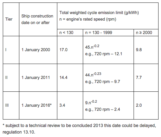
Progressive reductions in NOx emissions from marine diesel engines installed on ships is included in MARPOL Annex VI, with a “Tier II” emission limit for engines installed on or after 1 January 2011. NOx “Tier III” is more stringent emission limit for engines installed on or after 1 January 2016 operating in ECAs. Marine diesel engines installed on or after 1 January 1990 but prior to 1 January 2000 are required to comply with “Tier I” emission limits, if an approved method for that engine has been certified by an Administration.

NOx Tier III  emission standards are 80% less than NOx Tier I emission standards.

The emission value for a diesel engine is to be determined in accordance with the NOx Technical Code 2008 in the case of Tier II and Tier III limits.

As per Marpol Annex –VI Tier III limits are :

For Engine Speed less than 130 rpm – 3.4 gNOx/kwh

For Engine speed 130 and above but less 2000 rpm – 9*n-0.2 gNOx/kwh

For Engine speed above 2000 rpm – 2 gNOx/kwh.

MARPOL NOx Tier III

Image Credits: IMO.org

NOx Tier III emission standards are applicable only in NECA (NOx Emission control areas ). Outside NECA , Tier II standards are applicable. Current NECA areas are the North American area and the U.S. Caribbean area.

Tier III standards will also be applicable to ships built on or after 1 Jan 2016.

Are the ships ready for the emission standards?

To comply with this Tier III requirements ships shall have to be installed or retrofitted with equipment/systems which can reduce NOx below Tier III standards.

Mentioned below are seven technologies available to meet this criteria.

 1. Selective Catalytic Reduction (SCR)

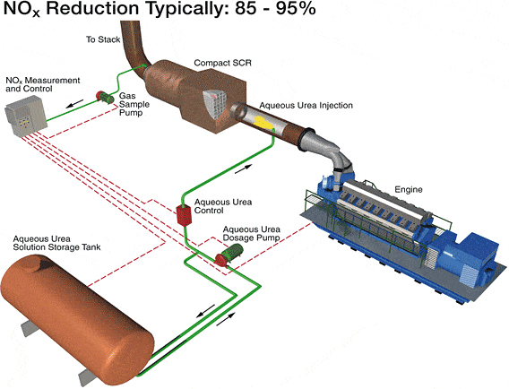
In this system, urea or ammonia is injected in the exhaust gas before passing it through a unit, which consists of special catalyst layer, at a temperature between 300 and 400 Deg C. Chemical reaction between Urea/ammonia and NOx in exhaust gases reduces NOx (NO and NO2) to N2. SCR unit is installed between the exhaust manifold/receiver and the turbocharger.

High efficiency turbocharger is required for this system as there is pressure drop across SCR Reactor. Engine load should be 40% and above, as NOx is reduced to N2 within specific temperature window ( 300-400 Deg C).

If temperature is above 400 Deg C, ammonia will burn rather than reacting with NOx which will lead the system to be ineffective. If the temperature is below 270 Deg C, the reaction rate will be low and the ammonium sulphates formed will destroy the catalyst.

Selective Catalytic Reduction

Image credits: vikingline.com


->Some B&W engine uses DeNOx or SiNOx system using SCR technology.

->Some Wartsila engines also has NOR (NOx Reduction) system that uses SCR technology.

More than 90% reduction is achieved by using SCR technology to comply with Tier III emission standards.

 2. Exhaust Gas Recirculation (EGR) :

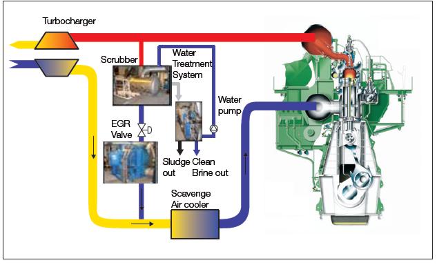
In this technology, part of the exhaust gas after turbocharger is recirculated to scavange receiver after passing it through the scrubber ( exhaust gas washing ) unit. Around 50-60% NOx reduction from tier I is claimed by making use of EGR. However discharge of cleaning water requires treatment like purification and separating exhaust gas cleaning sludge. As some countries are against discharge of this water, re-using this water poses corrosion problem.

NOx reduction takes place due to reduction in excess air (oxygen content) used for combustion, addition of CO2 and water vapour reduces peak temperatures as both have higher specific heat than air.

EGR system along with combination of one of the technologies such as altered (delayed) injection method, new design fuel valve, common rail injection principle, electronic engines , Scavange Air Moisturizing, can be used to comply with Tier III standards.

Exhaust Gas Recirculation

Image credits: Greenship.org

3. Scavange Air Moisturizing :

Air from the turbocharger, after passing through the compressor, has high temperature. Seawater is injected to this high temperature air for cooling and making it saturated. Distillation process makes it possible to use sea water instead of fresh water. Humidification of air is controlled by maintaining scavenge air temperature between 60-70 Deg C. Water in saturated air reduces the peak temperature as water has higher heat carrying capacity than air.

Around 60% NOx reduction is achieved by this method. By using combination of other technologies such as EGR  with Scavange Air Moisturizing, NOx Tier III standards can be achieved.

4. Miller Cycle :

By making use of Miller cycle in 4-Stroke engines along with high efficiency turbocharger, that is, early closing of inlet valves before BDC, causes expansion and cooling of intake air which reduces NOx production. This NOx reduction method will require two turbochargers ( 2-Stage turbocharging).

This method along with Direct Water injection (DWI) Principle and other methods such as fuel water emulsion can bring NOx well below Tier III standards.

5. Use of Low Pressure Gas Engines :

New marine engines using low pressure LNG as marine fuel will have greater importance in meeting Tier III standards. Wartsila has developed 2-stroke DF technology engine which makes use of low pressure LNG as fuel. It is based on lean-burn principle (relatively high air/fuel ratio), in which, the pre-mixed air/fuel charge is ignited by pilot fuel. One of the most important aspects of this engine is that the emission are below NOx Tier limit, and this is achieved without use of exhaust gas treatment system.

6. CSNOx : Ecospec have developed a system known as CSNOx which uses fresh water or seawater to pass through Ultra Low Frequency Electrolysis system. This treated water is further mixed with to react with the exhaust gas to reduce NOx content. The system reduces CO2, SOx and NOx in one compact equipment. This technology along with other NOx reducing methods mentioned above can be used for compliance with Tier III standards. CSNOx has an advantage of achieving high efficiency with low maintenance and power consumption.

cosnox

7. Combination: Combination of Technologies having one or more combinations such as electronic engines with variable fuel timings, LNG as fuel or Direct water injection or Fuel in water emulsions etc with other NOx reducing methods can be used to comply with Tier III emission standards. These mentioned combination may or may not require exhaust gas scrubber to comply with Tier III norms.

Over to you..

Do you know any other important method that can be used to reduce NOx production? Let’s know in the comments below.

How Earth Observation Satellite Services can help Increase Maritime Security?

$
0
0

In the ever changing times today, just as much benefit can be drawn from the maritime industry, the same number of threats is faced by the industry every single day.

Maritime security, may it be concerns related to marine environment or the rising piracy activities around the world, is put into jeopardy by a number of factors such as

  • Piracy
  • Oil spillage
  • Changes in ocean currents
  • Shipment debris
  • Rerouting of the ship
  • Ice accumulation on ship route
  • Loss of track

Image Credits: firetrench.com

These are only some of the threats faced by the industry and the maritime professionals working out on seas every single time. Of these, some are beyond human control like an unexpected storm, whereas some are man-made and can be easily controlled. When a storm comes, there is nothing one can do to stop it rather than finding ways to escape it.

However, there are some threats that can be detected and with suitable efforts, crew can be protected from them. Such Types of threat are piracy at sea, loss of tracks of ships etc. For any kind of threats faced by ships today, however, there is one coherent solution- earth observation satellite services.

Satellite services are not new by any means. They have been around for a long time now, having helped humans understand earth and atmosphere in a way not possible otherwise. Sure that makes them very useful but when put to a little more use, they can reveal much more than secrets of orbits of various planets. Special class of satellites based on principle of remote sensing can be extremely advantageous when it comes to making maritime industry safer.

Against natural factors

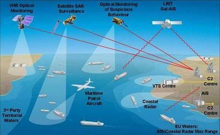
Satellite services can be extremely useful when it comes to providing protection to shipping industry against a danger of natural disaster that they constantly live in. These meteorological satellites can be used to update ship’s crew constantly about their route and chances of hitting an unfavorable situation.

They can closely monitor clouds, ocean currents, energy flows, ice covers over the sea and movement of storms. This information can be used to warn the ship about any such approaching natural disaster so that preventive measures can be taken appropriately.

Against oil spills

Oil spillage happens to be one of the major risks to maritime security. Regions of excessive oil spill can turn dangerous for ships passing through those regions, endangering lives of not only marine animals of the area but also of everyone present on those ships.

With geospatial satellites that can view the earth’s surface, both land and water bodies very closely, sometime even up to few centimeters of surface can study the ocean surface constantly. They can also study color differences in the images of oceans taken constantly from the space.

These images can further be studied and quickly relayed to other regions through the interoperable geospatial arrangement. Spot imaging along with an efficient system of interconnected centers on earth can make any information collected anywhere on the earth available to a broad community even in less than two hours. The real time imagery through spot imaging can be used to supplement the already available material for marine protection. This can be extremely helpful in averting serious accidents and improving maritime security a lot.

In vessel tracking

Keeping a constant track of vessels is very important both from economic aspect and from the point of view of safety of mariners on that vessel. Vessel tracking systems based on satellite sensory technique makes basis for the satellite based GPS monitoring system that helps in keeping a constant tab on position of vessels at all times.

This helps in knowing the exact location of the vessel. However, in case of a ship being lost on the track, satellite tracking of the vessel through AIS happens to be the most efficient way of finding the location of a lost vessel. Coast guard security can contact a satellite data company any time to seek information of any vessel. They work as a two way communication system enabling lost vessels to contact anyone through these satellites.

Maritime piracy

Piracy at sea is a greater danger to ships than many others. Recently, the incidences of maritime piracy have increased manifold. Report on piracy at sea says that this is mainly due to inadequate ways of combating maritime piracy. However, satellite services can be used as one major way to lower this number.

Satellite imaging can detect any incoming inhospitable objects. This, when combined with other anti encounter measures taken on the ships can increase security against maritime piracy to great extent. Geostationary satellites that allow remote sensory imaging in NRT (near real time) can relay information to different parts of the world.

The interconnected systems between coast guards along with security measures like onboard security, armed personnel, deck patrolling etc can together make an efficient security system. The report on piracy can begin to show a downfall in graph of pirate attacks with use satellite services to combat it.

You may also like to read: The Long Range Tracking and Identification (LRIT) System

References: nec, ceon-bremen, enotes, spotimage

How Marine Air Charging System For Engines Has Changed Over Time

$
0
0

Diesel engine for propelling ships came in to picture in the early 19th century.  They not only helped to reduce the heat losses (steam engines) from engines but also to increase the speed and fuel efficiency of the ships.

For efficiently burning diesel fuel in the engines, it is imperative that sufficient air is supplied at every cycle inside the cylinders. To achieve this, a variety of methods were adopted for supplying fresh air to burn the fuel and to produce the required power within all cylinders of the engine.

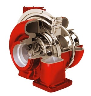
turbocharger

Before turbocharging came, the process of supercharging process was used. A mechanical arrangement within the engine was used to supply extra air to the combustion chamber of the engines. In this article, we will discuss different methods and arrangements used to supply fresh charge air:

diesel engine

1.Mechanically driven side mounted air pumps: In early 1900s, engineers made it possible to supply additional air using mechanically driven side mounted air pumps. These pumps had a belt attached to the crankshaft of the engine which supplies the fresh air taken from the atmosphere

2. Side mounted pumps for each unit: Then came the side mounted pumps for each unit, which is driven by levers attached to the crosshead of the engine piston rod assembly. This arrangement was quiet popular to supply scavenge air in to the combustion chamber

Lever Pump

3. Roots type blower pump: It was followed by use of Attached roots type blower pump having two lobe type rotors supplying fresh air to the engine.

Roots_blower_lobes

4. Electric motor driven blower: Electric motor driven blower for engines, which are used till now to provide initial charging air during the start of the engine, were then used.

5. Scavenge ports: Scavenge ports provided in the cylinder liners are widely used in old marine engines to charge the combustion chamber with fresh air when piston is in its downward motion.

Liner with Scavenge ports

6. Turbocharger: Turbocharger, the most efficient machinery to provide charge air for combustion purpose and which is now used in all marine engines (2stroke and 4 stroke), was prominent in 1950s and is still used with a supercharging system in 2 stroke engines (engine blower)

7.Two-stroke turbocharger: Two-stroke engine turbocharging is achieved by two distinct methods, respectively termed as the ‘constant pressure’ and ‘pulse’ systems. It is the constant pressure system that is now used by all low speed two- stroke engines.

8. Scavenge air coolers: With the increase in demand of power for marine engine, it became important to control the temperature of the combustion chamber and hence scavenge air coolers were placed in between the turbocharger and engine cylinder.

ME AIR COOLER

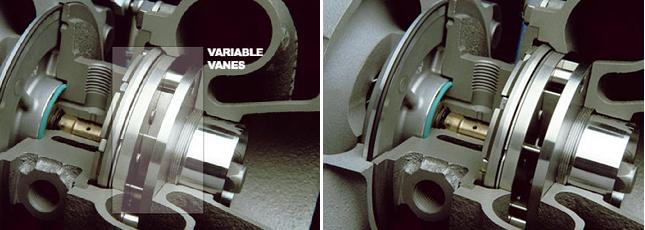
9.Variable geometry turbine: Variable geometry turbine (VTA) is the new age technology which can work at low engine load and eliminate the requirement of additional engine blower from the system. The VTA provided with movable vanes are replaced with conventional fixed vanes, which can change angles to control the exhaust flow on the turbine blades. This helps the engine control to balance the volume of air with the fuel along the entire engine load range.

10. Dual or Two stage turbocharger: In today’s time, the ship owners have to ensure that the pollution produced by ship’s engine is under control. One such turbocharging system used for this purpose is the Dual or Two stage turbocharger, which reduces the harmful NOx emissions from the engine by 80%. There are two different sizes of turbo chargers arranged in series which provides higher pressure ration than that provided by the best available single stage Turbo charger.

The turbine from the smaller turbo charger unit is positioned upstream of the turbine of the larger unit from the engine exhaust flow system. For air side, bigger turbocharger compressor is fed into the smaller unit’s compressor. Inter cooling system is provided in between the two stages which reduce the temperature and the volume of the outlet air. This allows 2nd unit to be smaller making the whole system compact.

Credits: Man.eu

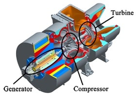
11. Hybrid turbocharger: Hybrid turbocharger is developed by Mitsubishi heavy industries and it differs from conventional turbochargers in terms of both waste recovery and fuel saving. Exhaust gas energy is recovered to turn the compressor, which supplies scavenge air to the main engine and also generates electricity through an alternator attachment incorporated in the turbocharger known as MET hybrid turbocharger

Internal parts of hybrid turbocharger

The air charging in modern marine engine is now done by Constant pressure turbocharger or by VTA turbocharger. With more sophisticated system being implemented on the engine, we may see a different breed of these high speed, fuel saving machinery in near future.

Over to you..

Do you any other air charging technology used in marine engines? Let’s know in the comments below.

7 Underrated Marine Technologies That Can Give Promising Results

$
0
0

Just like in any other industry, research and development consume a majority of investments in the maritime industry as well. With introduction of stricter environmental norms and regulations in the industry, shipping companies are taking the best of help from the latest technological advancements to reduce their carbon footprints and increase the ship’s overall efficiency.

In the last decade, the maritime industry has seen a myriad of technological innovations aimed at reducing carbon emissions from ships, improving fuel efficiency, and making machinery systems more reliable. Many of these technologies either failed to get implemented or faced delays in the development process.

But there are a few great innovations that have proved their mettle with the constantly changing norms of the maritime industry. The only point is that they are still not being used as extensively on ships as  they should because of a few drawbacks.

Mentioned below are seven such exceptional technologies that would become an integral part of maritime industry in future if implemented and utilized in the right manner.

1. Hybrid Turbocharger for Marine Engines

hybrd turbocharger

Ever thought of drawing energy from a marine system which is already an energy recovery system? Well, the hybrid turbochargers for marine engines does exactly that. A system which does not use fuel directly and still generates power is something that will be admired by all, especially when the fuel costs are ever rising. However, this great technology is not being extensively used as it is expensive and complicated as well. If used in the right way, they can produce some great results.

Know more about hybrid turbocharger here.

2. The “Cutting Edge” Emergency Propulsion System

We have often heard of situations wherein the ship’s main engine has shut down in mid-sea, causing the ship to go out of control. In case of grounding or any other kind of accident, shipping companies have to spend thousands of dollars in towing the ship to the nearest port. An innovative emergency propulsion system works great in such situations without the need of tugs. In this system, the propeller shaft is attached to a motor during emergency to propel the ship to the nearest port.

3. COMPAC Stern Tube Bearing System

There are two main things shipping companies are afraid of – Oil pollution from their ships and high cost of maintenance. It is a known fact in the industry that the maintenance of ship’s stern tube system is an extremely costly task which every ship has to undergo in dry docks (once every 3 years). Moreover, there are high chances of oil leakage from the stern tube whenever the ship’s draught is less.

The revolutionary COMPAC Stern Tube Bearing System gives a maintenance-free run of 10 years and uses water for lubrication, saving cost of lube oil and eliminating any chances of oil pollution.

Know more about this stern tube bearing system here.

4. Lambda Control

Just like oil pollution norms, there are air emission norms which every ship has to comply with.  However, it is not always possible to control the amount of smoke emitted from the ships especially from generators during start-up and when there is load variations. Port authorities often come on board ships to complain about thick smoke coming from the funnel.  Lambda control supplies additional air during start up period which reduces the black smoke by minimizing improper combustion.

However, since it is an additional system and not a requirement, very few ship owners actually think of  installing this control system. The lambda control is a smart solution to reduce such kind of problems, including the maintenance cost of the machine.

Know more about Lambda Control here.

5. Reverse Osmosis: Modern Alternative for Shipboard Water Production

Reverse Osmosis is a famous system for land based operations. The system has its own advantage over conventional water production on ships, especially for those with high water demands (cruise, platforms etc.). Moreover, it also produces purer form of fresh water than that produced by conventional methods used on ships. Drawbacks such as high  installation costs of the plant and inability to utilize the waste heat energy (from jacket water) unlike that in conventional heat-exchanger type fresh water generators (FWG), makes this system not so popular in the maritime sector.

Know more about reverse osmosis process here. 

6. S- Separators for Fuel Oil

Known to be one of the most trusted and famous brands for supplying separators to the shipping industry, Alfa Laval claims that their S -separator is highly reliable and has lowest life cycle cost. With disc modifications and added enhancements to the disc stack among other improvements, this  allows up to 20% more flow with retained separation performance. This is a highly advanced separator for ships and should be used more often.

Know more about Alfa Level S Separator here. 

7. Variable Geometry Turbocharger (VGT)

Not so underrated, but still not very visible in the industry, VGT is a revolutionary technology, patent of MAN diesel and turb,o which allows marine engines to improve fuel combustion and efficiency even at slower speeds. In the age of slow steaming this technology is a boon for marine engineers on board ships and also for the shipping companies. The VGT also helps in reducing the NOx emission from the ships and there is no requirement of an auxiliary blower in the engine.  Morever, VGT is a MAN technology and the other major marine engine manufacturers use conventional turbochargers that don’t have VGT. 

Know more about Variable Geometry  Turbocharger here.

Do you know about any other marine technologies that aren’t being used as much as they should be?

10 Situations When Ship’s Generator Must be Stopped Immediately

$
0
0

The generator onboard, being the powerhouse of the ship, requires regular maintenance and overhauling to ensure efficient and safe operations. A responsible marine engineer will never wait to carry out maintenance procedures until its machinery is on the edge of a breakdown. Instead, he/she will take all necessary precautions to prevent his ship from any impending troubles, which can take place because of engine room machinery failure or breakdown.

There is a thin line between the starting of a problem and the problem taking the shape of a major issue.  It is only a ship’s engineer who can assess this situation.

Still, cases are observed every year wherein the auxiliary engine breakdown occurs even after giving several indications, foreboding the unfortunate.

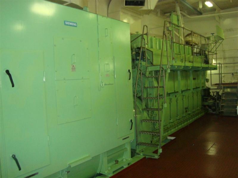
Marine generator engine

Listed below are ten cases wherein you must immediately start the standby engine and stop the auxiliary engine in “trouble” before a dangerous situation takes shape of a major disaster:

1. Abnormal/ Queer Sound: The ship’s generator engine comprises of heavy oscillating and moving parts. The attached auxiliaries such as turbochargers, pumps etc. are also high-speed machines which produce a good amount of sound. Any abnormal sound, no matter how faint, must never be ignored. In case of an unusual sound, the engine should be immediately stopped and troubleshooting must be carried out.

Incorrect Approach: The engine room is equipped with hundreds of machinery systems. When the power-plant is in operation, sounds from other machinery can suppress an abnormal sound. Even if you hear something unusual from the generator, you may think it’s coming from nearby environment or machinery. Never ignore even the slightest abnormal sound. Take a second opinion and stop the engine for checks.

2. Smoke: When you see smoke coming from or near the generator, it’s high time to stop the generator immediately. No need to offload the generator as the situation has already passed the danger level. Use the emergency stop button provided in a local or remote station. Smoke can be due to friction between moving parts, overheating etc.

Incorrect Approach: PANIC is the first thing that will strike a person when smoke or fire is seen. It might reduce the engineer’s thinking process, which will eventually slow down the approach.

Never panic in such situation. Use the remote start button for the standby generator, which will come on-load almost immediately (normally done through local), and emergency stop the running generator.

Ship's Generator

3. Unusual Lubricating Oil Parameters: If the lubricating oil temperature has increased beyond normal or the oil pressure has dropped below the adequate level, stop the generator immediately and find out the troubling issue, which might be a dirty lube oil cooler or chocked filter.

Incorrect Approach: If you noticed a drop in pressure, the first thing comes to mind is to change to standby filter. If your standby filter is not primed and put in service in running condition, due to airlock major bearing damages can occur. It’s always better to stop the machinery and then change it to standby filter, only after priming the same.

4. Higher Differential Pressure: Differential pressure is a term used to assess the condition of lube oil filter by providing a pressure measurement before and after the filter. The difference between the before and after filter pressures is displayed by a gauge. If the differential pressure is in the higher range, stop the generator and change to standby filter.

Incorrect Approach: On numerous occasions, it has been observed that the generator is allowed to run even when the differential pressure alarm is sounded during maneuvering. Engineers usually prefer not to take risk of changing the filter in running condition, as it may lead to blackout if the filter does not perform correctly. They thus plan to change it once the maneuvering is over.  However, due to this sometimes the differential pressure increases further and there is a sudden drop in oil pressure, which trips the generator in between maneuvering. It is very much possible to find bearing metal particles when filters are opened for cleaning. This shows that most of the times engineer is aware of the filter problem but fail to see the bigger picture.

5. Overspeed: Generator is a high-speed machinery and over-speeding of generator engine has resulted in explosions and causality in the past. Over-speeding of the generator is caused mainly due to a problem in the fuel system, specifically malfunction of the governor. If the generator is running above its rated speed and still does not trip (Read about overspeed trips here), engineers must stop the generator immediately to avoid a major accident. Crankcase inspection and renewal of bottom end bolts is then to be carried out.

Incorrect Approach: During trial running of generator after overhauling, the governor droop is altered to get required speed as stated in the manual. It may happen that the generator over-speeds due to wrong setting or due to stuck fuel rack during this time. Cases of not checking the crankcase and not renewing the bottom end bolts are common causes which lead to bearing damages.

6: Cooling Water Supply: Cooling water supply is an essential entity to ensure a smooth running of all high temperature moving parts. If there is no cooling water supply due to the failure of pumps, the generator should be stopped immediately to avoid overheating damage.

Incorrect Approach: If there is no cooling water pressure in the line, sometimes engineers try to release air from the purging cock provided near the expansion tank line of the generator. If the water supply is not available (due to the failure of supply pump), it will lead to further increase in the temperature and stopping of the generator at a later stage, resulting in the seizure of moving parts. Always stop the generator first and then do the troubleshooting. Once the generator is stopped due to starvation of water, flywheel should be rotated with lubrication to avoid seizing of parts.

7: Leakage from Pipings: If any leakage is found from the fuel, lube oil or cooling water pipe, it is to be rectified only after stopping the generator. This will allow the engineer to tackle the leakage easily and better maintenance can be carried out.

Incorrect Approach: If there is a small fuel oil or a water leak from any of the pipe connections, tightening of the connection may stop the leak but over-tightening may lead to a sudden increase in the leakage and with high-temperature fuel and water splashing, it can cause a severe burn to the operator skin.

8. Vibration and Loose Parts: Vibration is one of the main causes which increase the wear rate of moving parts. If loose bolts are found or heavy vibration is detected when the engine is running, stop the generator engine immediately and find the cause for rectification.

Incorrect Approach: It is not a common practice to check the tightness of the foundation bolts of the generator and its attached auxiliaries such as turbocharger etc. on ships. It has been found that many shipping company’s PMS do not include the foundation bolts and other bolts tightening checks in the routine.

9. Non-functional Alarms and Trips: During any point of time, if an alarm of the running generator is detected not to be working, then the generator needs to be stopped immediately as there is a possibility that other important alarms and trips are also not working. This can lead to major failure if an accident occurs in the generator.

Incorrect Approach: Ship crew on several vessels have a tendency to ignore alarms which they think are not important. It is many times observed by Port State Control (PSC) that generator alarms and trips are either not working or wrongly set. Such situations will do no good in saving the generator from disaster. Check all the alarms and trips on weekly basis.

Ship's Generator

10. Water in Oil: Water leaking in oil will decrease the load carrying capacity of the oil and leads to bearing damages. In such cases, the generator must be stopped if the water content is very high. Immediately find the leakage and renew/purify the sump oil before bringing the generator back in operation.

Incorrect Approach: Several cases have been found wherein the generator lube oil tests were not carried out regularly and the generator was allowed to run with water content in the oil. The effect of small amount of water is not immediately seen, but it will corrode and damage important parts of crankshaft and bearings in the long run.

The stopping of the generator is not limited to above points. There can be several other reasons which would require generators to be stopped immediately. However, it is the duty of the engineer to use his expertise and knowledge to avoid any kind of breakdown well ahead of time.

A wise engineer always think of the worst and hope for the best!

Over to you…

Do you know any important sign which suggests the ship’s generator should be immediately stopped?

Let’s know in the comments below.

10 Boiler Operating Mistakes On Ships That Can Cost Big Time

$
0
0

Every engine room machinery system requires a specific procedure for starting and stopping it. Boiler being one of the most important systems on board ships, requires special care and attention during operation and maintenance. Inability to do so leads to major failures and accidents, which can not only be life-threatening but also cause huge damage to the ship’s properly.

Mentioned below are 10 boiler operating mistakes that can lead to heavy loss of life and properly on board ships:

1. Starting a Boiler Without Pre-purging the Furnace: Almost all boilers come with an automation system of starting and stopping comprising of programmed pre-purging and post-purging of furnace before the burner is fired. Never ignore or isolate this safety feature. If the boiler has to run manually, it must be pre-purged by means of FD fan for at least 2 minutes. Avoiding this step can lead to blowback and even explosion.

Verticale Boiler

2. Ignoring Furnace Blowback: Several accidents in the past involving furnace blowback have lead to fatal situations on board ships. Still marine engineers often overlook this danger and fire furnace even when the first attempt ends with flame failure and blowback. One of the reasons for this is stated above i.e. no pre-purging of furnace.

3. Bypassing Safety and Alarm: This is a common practice among seafarers, who bypass some of the safety or automation sequences to shorten operating procedure of boilers. Such systems are installed to ensure safety of ship personnel and thus should never be missed.

4. No checks on Boiler Refractory:  Boiler refractory provides better heat-exchanging efficiency and closes/seals gaps to restrict fire, heat, ashes etc. inside the boiler . Regular inspection of boiler refractory is important as damaged refractory would expose the boiler shell to flame and heat, leading to bulging or even cracking of the boiler shell.

5. Dirty Gauge Glasses: Gauge glasses installed on the boiler are the only physical means to check the water level of the boiler. Every engineer knows the procedure to blow the gauge glass for avoiding any kind of blockage. Neglecting this can lead to wrong water level indication and heavy damage to boiler tubes.
INA boiler 2

6. Pilot Burner Check: Many engineers remove the pilot burner to check the electrode spark. Such practice can lead to electrical shock and even fire if the surrounding are not properly cleaned or the pilot burner is kept on oily floor plate with rags. The best way to check the pilot burner operation is to fit it in place and watch the firing from boiler inspection manhole located opposite of the burner.


7. No Clean-up After Burner Maintenance: When any maintenance work is done on the burner assembly (pilot or main burner) and the surrounding area is not cleaned before trying out the boiler, there are high chances of fire and explosion as blowbacks are normal during starting-up after maintenance. Oil spilled inside the furnace and over the burner assembly can add more to this blowback, converting it into an explosion.

8. Cold Condition – Thermal Shock: Never fire a boiler continuously when starting from cold condition to avoid thermal shock. Thus in cold condition, boiler should be started by following an intermediate firing pattern, for e.g.  2 minutes of firing followed by 10 minutes of break. Also, once the boiler starts to warm up the “break” time gradually decreases and the “firing” period increases simultaneously

9. Wrong Operation of EGB Circulating Pump: Exhaust gas boiler (EGB) normally comes with water circulating pump. It is important to start this pump well ahead, at least 2 hours, of starting the main engine and to be stopped 12 hours (the time may reduce depending upon the capacity of the boiler and the geographical condition) after stopping the main engine to avoid thermal shock and EGB fire.

10. Cleaning of EGB tubes:  The exhaust gas boiler (EGB) tubes are arranged in the passage of exhaust gases, which heats the water in the tubes. If these smoke tubes are not cleaned regularly, it can lead to soot deposits over the tubes and during low load operation or improper combustion oil can mix up with the soot. When ignited, the soot can lead to major soot fire followed by hydrogen or iron fire.

Are you aware of any other boiler operating mistakes that can be extremely dangerous to ship’s crew and property?

Let us know in the comments below.


Can Effective Predictive Maintenance Be More Beneficial On Board Ships?

$
0
0

Working in the maritime industry, we all know that planning and carrying out regular equipment maintenance is better than no-maintenance at all. But does that mean we would have to only rely on the planned or the periodic maintenance system that has been followed commonly by the whole fraternity.

Equipment and machinery especially the sea based ones are, more often than not, susceptible to failures, defects and the uncalled-for repairs. Maintaining them is hard work and particularly repairing the failed ones.

Thinking proactively, how would it seem if we try and eliminate unplanned failures and eventually the inflated repair costs by a method of early failure detection of the machinery while the equipment is still functioning normally. The question is whether the industry would follow a relatively less understood methodology called ‘Predictive maintenance‘ for all the ship’s running critical equipment and machinery.

Credits: fotolia.com

Credits: fotolia.com

Let us understand various types of maintenance programs used on ships that differ considerably from condition based monitoring –

  1. Periodic or Planned Maintenance System: This time based monitoring system is commonly employed on board ships that includes periodic inspection, overhauling, replacing components of a particular machine. It is costly and involves considerable man power
  2. Preventive Maintenance: In preventive maintenance, regular inspections, cleaning, lubrication, re-assembly is carried out as per the equipment’s maintenance schedule and conditional analysis which helps in retaining the equipment’s healthy working condition so as to prevent any further deterioration to the equipment.
  3. Breakdown Maintenance: Whenever a shipboard machinery fails or an equipment breaks down, the repairs that follow are known as Breakdown Maintenance. Generally a breakdown maintenance is avoided when at sea due to limited availability of resources unless the equipment is critical and in-use.

What is Predictive Maintenance?

Condition based maintenance or Predictive Maintenance is a proactive approach to solving unplanned interruptions due to equipment failure that eventually resulted in a costly maritime “downtime” affair. This approach is rather an abstract of predictions as compared to the preventive maintenance system followed religiously on board ships. The primary aspect of such maintenance is the pro active analysis that reveal and ascertain subsequent trends of the shipboard equipment or the machinery’s conditions, thereby warning us of the looming failure. This ensures that the ship’s staff understand the equipment’s current as well as future functioning abilities.

In short, it is a technique that helps us decide or predict the next maintenance cycle of the in-service machinery or equipment. It is also by far the most cost friendly approach when compared to the preventive or time based maintenance methods.

This technique detects any deterioration or the onset of it in a machinery that involves on board maintenance, aiding the less resourceful ship staff to be able to address any issues pertaining to its maintenance well beforehand.

internet

Internet on ship. © filigor – Fotolia.com

What are the advantages of Predictive Maintenance?

Predictive maintenance survives on trend values and relevant analysis. It acts as a surveillance system that is designed to detect the on-line conditions of the marine equipment and machinery.  Let us see some of the benefits this technique is designed for –

  • Ship staff would be well prepared to plan their maintenance schedule in order to curtail or even eliminate overheads
  • Inventories for stocks and spares will be minimised as the parts need not be asked for ‘in-advance’ that would otherwise be called for during machinery breakdowns
  • The technique will ensure that machinery or the equipment operates at an optimal operational level that would in turn save energy consumption and thereby the working costs
  • Intend increasing shelf life of the components, lasting longer and performing better
  • Reduction in unexpected machinery failures
  • Cut back in maintenance costs, repair costs, etc.
  • Increases marine plant capability
  • Prevents additional work load for the ship’s crew. Such techniques, in fact, raise the working morale among the crew members, as the crew becomes aware of the equipment status and its subsequent condition in the future
  • Promotes and consequently improves safe working culture on board due to the maintenance plan’s look ahead technique.
  • Ensures an Eco-friendly work environment with low energy consumption and high environmental safety

Ship marine engine

Why Predictive Maintenance over Preventive Maintenance?

Maritime Industry, today, focuses largely on having minimal shipboard failures, defects or breakdowns. Unplanned accidents are unavoidable but the least can be done is to prevent them from happening by way of predicting and analysing a future trend of the machine.

Whether we like it or not, PMS or Preventive Maintenance has to be carried out as per the program’s schedule even if the condition of the equipment is such that it does not require any frequent care. For example, frequently greasing / lubricating mooring winches on a large tanker that rarely berths alongside, isn’t going to increase the efficiency of its moving parts any better than it already is. The only thing it (lubricating the winches) reflects is that our PMS work sheets are completed and sent to the office for a revival of the same work order for the next cycle.

Predictive maintenance changes this. When the equipment is ‘in-service’, an analysis will be taken of its current or actual condition with a goal to predict the equipment’s future condition than having to work like robots to have the predetermined job schedule completed.

On ships that employ a limited crew, time management, utilizing available resources and prioritising important tasks is imperative to the proper functioning of the vessel. Condition Based Monitoring makes the job even simpler since the task is carried out with minimal intervention while the machinery is in its normal operating mode. If worked upon, a well engineered condition based maintenance program will without question prove successful to optimally manage a time bound work culture on board ships.

mooring

Following the same example as above, on a large tanker where mooring winches are rarely in use, the best predictive maintenance one could carry out would be to simply rotate the drums on its power every once a while and ensure its integrity is intact (no oil leaks found, cracks located, etc.), the bearings move freely, gears lock-in correctly, no squeaks are audible while it rotates and likewise. This method would then determine, whether additionally, it may be necessary to carry out any further preventive or be satisfied with the planned maintenance for the upkeep of the machinery.

Changing Lube Oil in a critical machinery may sometimes fall under condition based (predictive) monitoring or may be at times be followed as a planned or periodic technique depending on the machinery’s requirements.

Purging oil pumps before putting them in service is again a good example of condition based maintenance.

Nonetheless, we can conclude that a well organised maintenance program (predictive maintenance used in tandem to preventive maintenance) can prove to be substantially beneficial to the shipping company as well as the vessel’s staff. One should also understand that although predictive upkeep is a derivative of preventive maintenance and that it has a different role within the system itself.

The aim should be to provide effective tools and instruments that are capable to analyse trends and help us in making early and better decisions for the well being of the machinery or equipment when out there, at sea.

Over to you..

Do you think predictive maintenance is more beneficial over other maintenance methods on ships?

15 Pro Tips To Handle Emergency Generator On Ships

$
0
0

On ships, there’re a separate set of systems provided both on deck and engine room for emergency situations. Some of the most important emergency machinery and systems on board ships are – Emergency compressor, Emergency bilge suction, Emergency fire pump, Lifeboat, and Emergency generator.

As per the SOLAS requirements, all emergency equipment/systems must be tested frequently (general practice on a ship- weekly) to ensure they run smoothly when really needed, especially in an emergency situation.

Out of the all the systems, the emergency generator is one of the most frequently used machinery as a blackout situation can occur anytime on a ship.

Therefore, it is very important not only for the engineer officer but also for the deck officer/crew to know the ways of starting and testing the emergency generator, as per the regulations laid down under SOLAS.

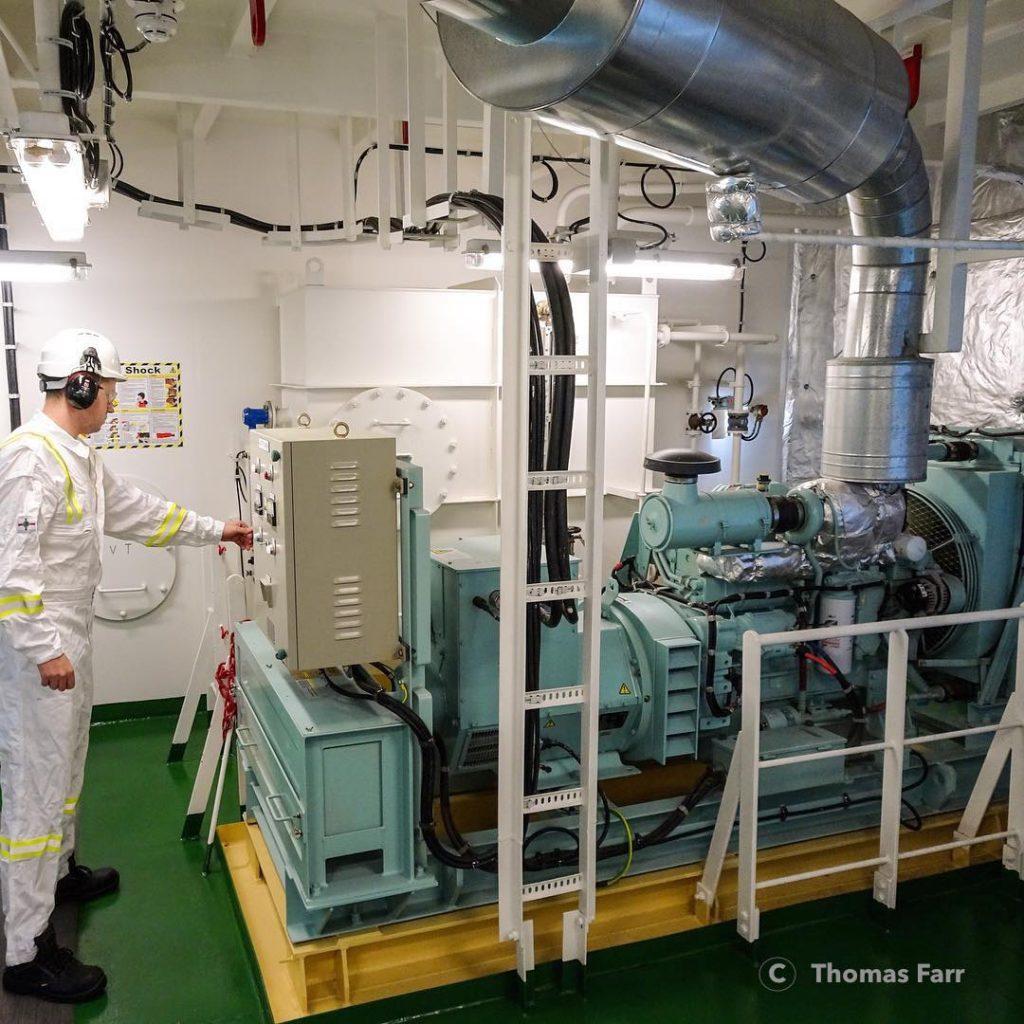
Emergency Generator

Image Credit: Thomas Farr

Important requirements for the prime mover of the emergency generator are:

  • The emergency electrical power providing generator shall be driven by a suitable prime mover having independent auxiliary systems, which may consist of fuel, ventilation, lubrication, cooling etc.
  • The fuel used in the emergency generator prime mover must have a flash point of > 43° C
  • The prime mover of the emergency generator shall be started automatically once the main source of electrical power supply fails
  • If the emergency generator does not start or does not take the load of the emergency switchboard connections, an indication shall be given in the engine room or at a manned control station

Related Read: How The Power Requirement Of A Ship Is Estimated?

Apart from complying with the SOLAS Ch II Reg 43, the important job of ship’s engineers is to maintain the emergency generator in top notch condition.

Following are the important points that should be remembered when handling emergency generator:

1. Anti-freezing compounds are added to the emergency generators to ensure it will start even at very low temperatures (-ve temperature). If using fully formulated anti-freeze compound, mix it with good quality water in a ratio of 1:1 or as stated by the manufacturer. If the fully formulated antifreeze compound concentration is kept higher than required, the cooling system may silica gel formation issue.

Related Read: What to Do When the Ship is Moving towards Sub Zero Temperature Area?

2. When mixing anti-freeze solution to the system, avoid pouring it alone in the radiator. It should always be mixed in the prescribed ratio with water before pouring into the cooling water system of the generator. This is because the potential of the ant-freeze liquid to remove heat is not as good as that of water and putting the anti-freeze compound alone in the cooling system may contribute to overheated condition before the liquids are completely mixed together.

3. Coolant is used in the engine cooling water system to control the overheating of the generator. They are added mixing with water. Never add coolant mixture at a low temperature to a hot engine. This may lead to damage to the engine casting. Always stop the engine and let it cool down before adding the coolant mixture.

Related Read: 8 Important Points To Note For Maintenance Of Emergency Generators On Ship

4. When adding the coolant mixture after a major overhaul or draining the cooling system, ensure to open the engine and aftercooler vent while filling the coolant to the system to allow air to escape and avoiding airlock

5. It is not a good practice to test the cooling water used in the emergency generator after a long interval of time. Ensure to test the cooling water quality every week and maintain it at a pH of 8 – 10.5 to avoid excessive scaling problem (if calcium and magnesium levels are more) or corrosion problem (if chloride and sulphate levels are more)

Related Read: 10 Important Tests for Major Overhauling of Ship’s Generator

6. Unlike auxiliary engine generator, the emergency generator should not be idled for a long period. Long idle timing (more than 10 minutes) will affect the fuel burning as combustion chamber temperature is very low. This will cause carbon clogging of the injector holes and sticking of the valve. The best idle time is considered to be 3-5 minutes for the emergency generator.

emergency generator

7. If the engine is idled for a long and the coolant temperature becomes too low (50-60 deg C), the fuel in the combustion chamber will remain unburnt and will wash the lubrication between piston and liner, causing damage to the moving parts.

Related Read: 10 Extremely Important Checks Before Starting Marine Engines

8. The most common problem found in the belts used in the engine to drive the water pump are cracks. Transverse cracks (cracks generated across the belt width) on the surface of the belt are acceptable within the prescribed limit. When the transverse crack is seen intersecting with longitudinal cracks, it is advisable to immediately change the belts.

Belt Cracks

9. The most common problem found in the radiator fan is the loosening of the screw, which connects blades to the rotor. Never stand in front of the fan (which is set up outside the emergency generated room, to open atmosphere) as a loose screw or broken blade may lead to a personal injury. Never try to rotate the engine using fan blades to avoid injury or breakage of blades itself. Always stop and isolate the engine before tightening the screw on the blade or doing any other maintenance on the fan.

Related Read: 10 Extremely Dangerous Engine Room Accidents On Ships

10. It is always advisable to fill the lube oil filter with lube oil (or fuel filter with fuel oil) before fitting the same to the emergency generator to avoid dry start-up.

11. If an emergency generator provided with compressed air start system, ensure the compressed air unit does not have any lube oil carryover. Prolong carriage of lube oil will form varnish and carbon deposits around the piston of the compressed air chamber and it will not allow it to seal and generate high pressure required for the starting.

Related Read: 8 Things Marine Engineers Must Know About Starting Air System On Ship

12. After a major overhaul, it is important to vent the air trapped in the high-pressure fuel line (of injectors). Each high-pressure fuel line to be vented separately by slightly opening the vent screw provided in the fuel line and by cranking the engine. If the engine needs to be started, ensure not to engage the starter for more than 30 seconds and provide a rest interval of 2 minutes before venting the next injector.

13. Avoid running with oil mixture atmosphere to prevent overspeeding of the generator or explosion of the internal parts. Such atmosphere is possible while loading hazardous cargo on the ship which can go inside the emergency generator through its air intake. Never mix gasoline or alcohol as it can cause an explosion.

Related Read: 10 Situations When Ship’s Generator Must be Stopped Immediately

14. After a major overhauling of the engine or when the Top Dead Centre (TDC) of the unit has to be marked, a locating pin is provided in most of the emergency generators which will sit in the hole of the gear drive attached to the camshaft, ensuring the first unit is in TDC. Once the TDC is located, ensure to remove the pin, else starting the generator will damage the pin and the locating hole

TDC Locating Pin

15. When the ship is plying in a low-temperature region for a longer duration, there is no provision to keep the emergency generator warm when it is not operational. It is advisable to use synthetic lubricating oil with low-temperature properties with low sulphated ash limit

Related Read: Important Lube Oil Properties to be Considered While Choosing Marine Lube Oil 

The make and capacity of the emergency generator vary on ships and the engineer must know the operational and maintenance procedure of the machine thoroughly. The above tips broadly remain the same for all emergency generator models fitted on commercial ships and in case of doubt or assistance, it is always advisable to contact the makers for recommendations.

Disclaimer: The authors’ views expressed in this article do not necessarily reflect the views of Marine Insight. Data and charts, if used, in the article have been sourced from available information and have not been authenticated by any statutory authority. The author and Marine Insight do not claim it to be accurate nor accept any responsibility for the same. The views constitute only the opinions and do not constitute any guidelines or recommendation on any course of action to be followed by the reader.

The article or images cannot be reproduced, copied, shared or used in any form without the permission of the author and Marine Insight.

Energy Conservation in Boilers and Making an Audit Report

$
0
0
marine boiler

In the last article in this series on the energy audit of the ships boiler, we discussed the instruments required for ship’s audit, pre audit precautions and the energy conservation and optimization opportunities. In this article we discuss the other opportunities for energy conservation and also layout of the final audit report.

Read the first two parts of the series here:

1. Energy Audit on Ships

2. Audit of Marine Boilers

Energy Conservation and Optimization Opportunities

The other areas where energy conservation and optimization opportunities exist are as follows:

marine boiler

 Performance of Heat Transfer Areas: The heat transfer areas of the boiler must be monitored. The soot blowing of the boiler must be done religiously as build up of soot acts like an insulator and reduces the heat transfer rate. That means for generating the same amount of steam more fuel will be needed. The same goes for the buildup of scale in the tubes. The stack temperature must be monitored regularly and any increase in it means that heat recovery is not optimum. If the funnel temperature increases about 40 deg C after last cleaning it indicates that boiler cleaning must be done.

Read important points on boiler cleaning here.

Heat Loss Due to Inadequate Insulation: The boiler and steam lines along with condensate return to the hot well must be well insulated. Over a period of time insulation is damaged or worn out. Any analysis by an infra red camera or infra red thermometer can identify the hot spots and optimize fuel consumption.

 Optimum Hot Well temperature: The hot well temperature must be maintained at temperature specified by manufacturers which is generally about 80 to 85 deg C. A lower temperature will cause colder feed water to enter the boiler thus increasing the fuel cost due to loss of sensible heat. An overheated hot well will cause vapor lock in the feed pump and loss of suction.

Learn how to troubleshoot marine boiler starting failure here.

Steam Trap Losses: Steam traps are used to discharge condensate once it is formed, to prevent live steam from escaping and to remove air and non condensable gases from the line. However it is a largely neglected part of the steam piping. Steam traps that are stuck open allow live steam to escape thus resulting in loss of heat and also increasing the load of the condenser. Steam trap that is stuck shut results in reduced capacity of the equipment it is being supplied to.

 Radiation and Convection Losses: The boiler body loses lots of heat from the exposed surfaces to the surroundings. In cold climate the loss is greater. Effective insulation can reduce these losses.

Optimize Boiler Steam pressure: Running a boiler at lower pressure after optimizing steam usage will lower the fuel consumption.

Installation of variable speed drives: The air dampers use throttling to obtain capacity control. These old methods of capacity control lack accuracy and have poor control characteristics at the top and bottom of the operating range. In case the steam demand of the boiler is variable and changes from time to time, then replacing the damper type air register with the new electronically controlled variable speed drive forced draught fan should be considered.

Understand marine boiler water circulation here.
Reducing Steam Leakage: Though this is a simply understood principle that steam leakage leads to energy and fuel loss, it is common to see many leakages of steam unattended due to either fear or apathy. Just by controlling the leakages many of the boiler operational problems can be avoided.

Audit Report on Energy Saving Measures

The audit report of the boiler must indicate the energy opportunities that can be availed, the investment required, the fuel saving and returns. The owner must be provided with the economic viability and feasibility of the project. The energy measures recommended are of three types.

Immediate Returns: Those energy saving measures that give immediate returns and require no investment. For example overhauling the burner, calibrating the air register, cleaning the tubes of soot, repairing steam traps etc.

Medium Term return:  Those energy saving measures that require moderate investment and give returns in a medium time frame.  For example these can be equipment modification like change of burner and air register, change of insulation, retrofitting the furnace with a new burner etc.

Long term return: These require considerable investment and will benefit in long term only. For example if the boiler is old and unusable, under or over sized. Replacing an old boiler with an energy efficient new boiler may be a good strategy. It is only recommended if the company has plans for keeping the ship for a long time.

Financial analysis of the energy saving measures is the most important part of a boiler energy audit. Annual cost savings from the upgrades, retrofits and replacements must be provided to enable the owner make correct decision.

References:

Boiler Operations  By M P Murgai and Ram Chandra

Training Manual for Energy Efficiency By Asian Productivity Organization, 2010

Presentation on Energy Audit in Thermal Power Stations by H.S.Bedi

Hand Book on Energy Audit and Environment Management by Y.P.Abbi and Shashank Jain

Working manual on Energy Auditing in Industries By Asian Productivity Organization


Marine Air Compressor Maintenance – Things You Must Know About

$
0
0
Intercooler

Marine air compressors are used to start large slow speed and medium-speed marine diesel engines, and therefore are an integral part of engine room on-board.

Generally, there are two compressors onboard a ship ( can be more than two depending upon the requirement of the vessel.)

The two compressors fill up the air receivers, which should have total capacity such that the engine can start 12 times ahead and astern without replenishment of the receivers. This capacity is limited to 6 times if it’s a unidirectional engine.

Each of the air receivers is fitted with a relief valve, which will limit the pressure rise to 10% of the maximum design pressure of the receiver.

Related Reading: Basics of air compressor on ship

Also, the outlet of the relief valves should be outside the engine room so that it doesn’t contribute in case there is a fire near the air receiver.

Marine Air Compressor
Usually, air compressors onboard are capable enough to charge both the air receivers from zero to full in one hour.

The air compressors are fitted with several safety devices as well such as relief valves on each stage which limit the pressure rise to 10% of the maximum working pressure.

The delivery side is fitted with a high-temperature switch which cuts off the compressor at a specified temperature or a fusible plug which may melt at 121 degrees centigrade.

Performance of the marine air compressor is taken at the end of every month to ascertain the working capacity of the compressor.

The performance report includes the delivery air temperature, cooling water inlet and outlet temperatures, lube oil pressure and discharge pressures of each stage of the compressor.

Related Reading: Efficiency Of Air Compressor

The compressor is generally started in an unloaded condition so that minimum current is drawn by the motor and the bearings are devoid of oil.

machinery ebook

Maintenance jobs carried out on the main air compressor depending on the running hours of the compressor and all these jobs are mentioned in the maintenance manual of the compressor.

  • The planned maintenance system devised by the company must be strictly followed else there can be a severe breakdown
  • To avoid breakdowns in the main air compressor, the following maintenance must be considered
  • Daily morning and evening rounds including checking of lube oil level, discharge pressures of various stages, discharge temperature and running time of the compressor.
  • When an engineer takes over, he/she must first take note of all the maintenance jobs that might be due in his/her contract, and take spare part inventory and order the spares, if required with the help of Chief Engineer.
  • The engineer must also note the torques required for tightening various bolts, screws and nuts on the main air compressor.
  • The testing of air compressor alarms must be carried out as per the PMS, which generally demands the alarms to be tested once every three months.
  • One of the most important things in the main air compressor is the bumping clearance of the compressor, which will be discussed later in the compressor maintenance.
  • As a basic thumb rule, the main air compressor should run for 3-4 hours every day on an MR tanker. If the running hours exceed this duration, then the required checks must be carried out.

Compressor Maintenance

VOLUMETRIC EFFICIENCY OF AN AIR COMPRESSOR

The volumetric efficiency of an air compressor is defined as the ratio of the volume of air discharged by the compressor as free air and the swept volume of the LP piston, whereas free air is defined as the air at atmospheric pressure and 15 degrees centigrade.

Related Reading: Starting and stopping procedure of air compressor

BUSTING THE MYTH ABOUT BUMPING CLEARANCE

Well, you might wonder about Bumping Clearance being marked in bold, here’s the deal:

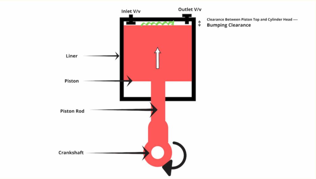
Bumping clearance is the top clearance in the main air compressor between the top of the piston and the cylinder head when the piston is at TDC.

This clearance is determined by the cylinder head gasket which should be of the correct size and indeed should be a genuine spare.

Related Reading: Top 5 Air Compressor Problems Marine Engineers Must Know

Bumping clearance is important as it relates to the volumetric efficiency of the compressor.

When the bumping clearance of the compressor is large then the clearance volume is big enough to accommodate a large volume of air when the piston is at the end of its stroke.

When the piston moves downwards, then a large amount of suction stroke becomes ineffective as the suction will happen only when the cylinder pressure falls below the atmospheric pressure.

Hence the piston stroke is wasted by expanding a large amount of air that has accommodated in the clearance volume due to a large bumping clearance.

Bumping Clearance
HOW TO CHECK THE BUMPING CLEARANCE? 

Generally, the bumping clearance of the compressor is fixed by the thickness of the cylinder head gasket used by the manufacturer but it could be measured by a lead ball placed between the top of the piston, assembling the compressor with the manufacturer recommended cylinder head gasket and taking the piston back to the top dead centre.

The ball will compress and then can eventually be measured by a micrometre. It is generally in the range of 1.2 mm to 1.8 mm.

FREQUENCY: 3000 RUNNING HOURS OR DEPENDING ON THE PERFORMANCE. 

HOW TO ADJUST THE BUMPING CLEARANCE?

Bumping clearance could be adjusted by changing the thickness of the cylinder head gasket or by adding or removing shims from the foot of the connecting rod and the bottom end bearing of the compressor.

CHECKING BASIC SCREWED CONNECTIONS

All the unions and screwed connections must be checked for tightness and must be re-tightened, if necessary.

This includes all cooler and airlines, unions on pipe and hose lines, cylinder heads, cylinders, electric motors, measuring and switching devices, bearings and other accessories.

FREQUENCY: EVERY 250 RUNNING HOURS.

REPLACING AIR FILTER CARTRIDGE

The air filter must be checked at frequent intervals and approximately at every 250 hours or whenever the air discharge temperature becomes high.

The air filter element must be replaced with a new one and sufficient spares must be available onboard.

An air filter is the first step to keep the compressor healthy.

It must be noted that the air compressors are installed at a place where there is sufficient air supply to ensure the suction is never devoid of air.

ONE MUST MAKE SURE THAT THE OLD CARTRIDGE IS NOT BLOWN WITH AIR AND RE-USED, AS THIS MAY DAMAGE THE AIR FILTER.

Dirty air filters affect the volumetric efficiency of the compressor and so does the temperature of the inlet air to the compressor.

FREQUENCY: EVERY 2000 RUNNING HOURS.
 

Air Filter Cartridge

CHANGING OIL

It is important that the oil must be changed according to the maintenance frequency as the lubricating oil is not only used for the lubrication of the running parts of the compressor but also to remove the heat generated during the operation of the compressor.

The compressor must be run for some time before the oil is changed as it ensures that all the sludge and particles are in suspension.

The oil should be completely drained by removing the drain plug and flushed with fresh oil before the oil is replenished back again.

The crankcase should be thoroughly cleaned as well with a lint-free cloth and must be checked for bearing wear as well.

TWO DIFFERENT GRADES OF OIL MUST NOT BE USED AND MIXED. 

FREQUENCY: 1000 RUNNING HOURS.

CLEANING OIL STRAINERS

The oil strainer is generally a mesh in a plate which is supposed to be cleaned at defined maintenance intervals. The filter should also be cleaned when the oil is changed.

It should be cleaned by a solvent and blown with air.

FREQUENCY: 1000 RUNNING HOURS.

CHECKING VALVES

This is one of the most important jobs in the maintenance of the compressor. Hence extreme care must be taken while carrying out this job.

WHEN REMOVING AND INSTALLING A VALVE, EXTREME CARE MUST BE TAKEN THAT NO VALVE PARTS ARE DAMAGED. THIS APPLIES TO THE SEALING SURFACES OF THE VALVE.

Different types of compressors have different types of valves and removal methods for different stages

The valves must be removed and should be checked for leakage with diesel oil or water

The valves must never be held on vice but should rather be held on the tool given for the same.

All the parts must be properly cleaned after opening the valve and they must be checked for the carbonization as well. Over carbonization reveals that the oil topped up is more than required. This would lead to the sticking of the valves and eventually they would break.

Sticking of the valves will also reduce the volumetric efficiency of the compressor as the quantity of air discharged would be comparatively lesser.

The valve plate should be checked by pushing the valve plate from the side of the valve seat by a screwdriver. The valve plate will move a distance which is equivalent to a valve lift.

The springs and valve plates should be changed if required.

The plate could be lapped as well if no spares are available.

FREQUENCY: 3000 RUNNING HOURS FOR THE DISASSEMBLING AND CLEANING OF THE VALVE. 3000 HOURS FOR THE REPLACEMENT OF THE VALVE PLATE. 3000 HOURS FOR CHECKING THE FATIGUE OF THE SPRING AS WELL. 

Related Reading: Troubleshooting Air Compressor On Ships
Air Compressor Valve
INSTALLING VALVES

All the valves must be re-fit with new gaskets and rings only. Only original spare parts must be used. Installing non-original gaskets may lead to compressor leaks and damage.

VALVES ARE THOSE PARTS OF A RECIPROCATING COMPRESSOR WHICH ARE MOST STRESSED, THUS THEIR MAINTENANCE MUST BE DONE CAREFULLY AND WITH EXTREME PRECISION.

HEAVILY CARBONISED VALVES DEPICT THAT THE LUBRICATING OIL HAS BEEN CARRIED OVER.

REPLACING VALVES

It is generally recommended by the manufacturer that the valves must not be repaired as they have a life and may fail due to fatigue. Thus, they must be replaced and the old ones disposed of.

The valves are supposed to be replaced in the same way as mentioned in the checking of the valves.

STICKING VALVES? WHY AND HOW DO THEY AFFECT THE COMPRESSOR? 

If a valve is sticking, then it might add to the woes of the compressor as a sticky suction valve might lead to a loss in the air delivered because a part of air will be returned back to the suction side (with the valve not seating properly because of the carbon deposit or the spring being defective).

Similarly, if the delivery valve is sticking then a part of delivery air might return back to the cylinder during the suction stroke of the piston.

VALVE LIFT TOO HIGH? HOW DOES IT MATTER?

The valves with too high a lift will take a lot of time to re-seat and hence are liable to break at the piston delivery stroke as the pressure might be high for the valves to sustain.

INTERCOOLERS AND HOW TO CLEAN THEM?

Intercooler

Intercoolers are generally arranged after every stage of the main air compressor to reduce the work done in compressing the air by successfully cooling it down between stages. The intercooler is generally in the form of copper tubes bent in a U form. The air passes through the tubes and water circulates around them. These intercoolers could be a single tube type or straight tube type.

These types of intercoolers are provided with purge-spots to collect and drain water/oil which might find its way to the air coolers.

The intercoolers are generally opened up as per the maintenance frequency and are supposed to be cleaned by a solvent and the integrity of tubes to be checked as well.

They’re provided with a bursting disc in order to relieve the pressure in case a tube bursts.

The single tube type coolers are difficult to clean and the rate of wear is more than the straight tube types.

The straight tube types, on the other hand, could be plugged if they leak.

FREQUENCY: EVERY 3000 RUNNING HOURS.

CYLINDER LINER, COOLING JACKET AND PISTON

The air carries a lot of moisture in the cylinder liner which could wash away the lubricating oil film from the liner, thus causing liner wear which could also result in the scoring of the liner.

Thus, proper draining of the compressor is necessary to prevent the excessive liner and piston rings wear.

Cylinder liners could be lubricated by the oil splashed from the crankcase. They could also be lubricated by lubricating oil quills similar to the main engine delivered by an engine-driven lube oil pump.

The piston rings could wear in due time causing blow past and eventually reducing the volumetric efficiency of the compressor.

FREQUENCY: THE CYLINDER LINERS ALONG WITH THE COOLING JACKET ARE TO BE INSPECTED/CLEANED IN EVERY 3000 RUNNING HOURS OF THE COMPRESSOR. PISTON, PISTON RINGS AND OIL SCRAPER RING TO BE CHECKED IN EVERY 6000 RUNNING HOURS.

LUBRICATING OILS

Different manufacturers have different requirements for the use of lubricating oils. The compressors generally do not permit the use of synthetic lubricating oils with 3 stage air-cooled compressors because the good hydrolytic properties of synthetic oils cause moisture to condense in the crankcase thus there is a risk of corrosion and drive damage.

Because of their design, 3 stage air-cooled compressors have low final compression temperatures, rendering the high-temperature stability of synthetic oils useless.

THE JOBS ARE MORE OR LESS SIMILAR FOR ALL THE COMPRESSORS BUT AN INSTRUCTION MANUAL MUST BE STRICTLY FOLLOWED BEFORE CARRYING OUT ANY MAINTENANCE ON A COMPRESSOR.

Related Reading: Procedure For Starting Breathing Air Compressor

Disclaimer: The authors’ views expressed in this article do not necessarily reflect the views of Marine Insight. Data and charts, if used, in the article have been sourced from available information and have not been authenticated by any statutory authority. The author and Marine Insight do not claim it to be accurate nor accept any responsibility for the same. The views constitute only the opinions and do not constitute any guidelines or recommendation on any course of action to be followed by the reader.

The article or images cannot be reproduced, copied, shared or used in any form without the permission of the author and Marine Insight. 


What Are Magnetic Strainers And Filters?

$
0
0
Filter After Pump

There’s a major misconception about the word filters when it comes to marine engineering equipment. As an equipment which carries out filtration is called as a filter but indeed this word is a misnomer and this may appear legit when you understand the concept behind it.

Filters and Strainers – What is the difference?

Filters and strainers both substantially filter out the contaminants in fuel oil, lubricating oil and water onboard a ship but there’s a fine line of difference between filters and strainers as the latter are installed on the suction side of the pumps to prevent the contaminants, debris or foreign matter from entering and damaging the running parts of the pumps.

Strainers are generally of the full flow type and hence their application is entirely different from the filters.

Strainer in Pipe Line

Filters on the contrary are fitted on the discharge side of the pumps and could be of the full flow or by-pass type.

The media filtered is generally the foreign particles or contaminants which are diminutively small and are unable to be filtered when in circulation.

A clean strainer causes a drop in pressure in the line which could be attributed to the rate of flow, the viscosity of the fluid being filtered, the size of the filter and the size of particles being removed.

Filter After Pump

Filter After Pump

There is a distinct type of filter called as auto back filter which works on the principle of pressure drop before and after the filter. The auto back wash filter cleans itself when the pressure drop increases beyond a certain value by blowing back air from outside to inside.

Related Read: Viscosity Meter and Viscosity Controller Used on Ships

These filters could be of various types mainly simplex filters, duplex filters, by-pass and full flow filters.

A simplex filter is a simple basket filter which is fitted in the line; a duplex filter is arranged in a pair and hence one filter could be used and the other could be cleaned and kept as stand-by; a bypass filter takes a part of the fluid from the line, filters and returns it back to the suction side of the pump; while a full flow filter takes the complete amount of discharge from the pump for filtration.

Several precautions are taken before cleaning these filters and the instruction manuals should be adhered to before opening them.

Fuel Oil Duplex Filter

Fuel Oil Duplex Filter

Thus, the fluid is treated accordingly before it could be filtered by a strainer to get the maximum separating efficiency.

Fuel oils and lubricating oils are generally heated before filtration as the specific gravity of the constituent particles reduce with the increase in temperature.

The specific gravity of the oil is reduced at a greater rate than the specific gravity of the contaminants and hence the difference in the specific gravities is comparatively higher when the oil is heated which aids in the filtration process.

Related Read: Filters and Strainers on Ship – Types and Uses

Classification of Contaminants

The contaminants, mainly metallic in nature are divided into three main categories, diamagnetic, paramagnetic and ferromagnetic.

Diamagnetic materials are actually repelled by the magnets and in extreme cases, weakly attracted to the magnets when subjected to very strong magnetic fields. Further, these materials do not retain the magnetic properties when the external magnetic field is removed.

Paramagnetic materials on the contrary are weakly attracted to the magnets and do not retain the magnetic properties when the external magnetic field is removed.

Ferromagnetic materials on the contrary are strongly attracted to the magnetic fields and retain the magnetic properties when the external magnetic field is removed.

Strainers act as the first point of contact for the removal of impurities and hence are supposed to run clean.

Magnetic Strainers and Filters

Fuel oil filters are generally fitted with cylindrical bar magnets to attract the magnetic particles present in the fuel oil. The magnetic particles include small iron particles which are not included in the BDN and go neglected.

The iron particles are tested by the IP 501 method by an approved lab ashore. These particles are minutely small and hence cause the wear of the moving parts of the engine. The iron particles are generally in the range of 0-50 ppm in the fuel.

Magnetic Filter

Image Credit- eclipsemagnetics.com

The magnets could be found in the purifier feed pump filters, transfer pump filters, fuel oil supply pump filters and fuel oil circulating pump filters. Thus they’re called as magnetic filters.

It must be understood that the lubrication of the running parts of the pump is carried out by the fuel oil itself, thus the fuel should run clean to avoid the wear of the same.

A gear pump running inside the casing has very small clearances between the gears and the casing. Wear may hence decrease the efficiency of the pump as the fuel will return back to the suction side of the pump causing a reduction in the pressure delivered.

The fuel pumps are mainly responsible for delivering the fuel to the injectors in an engine which indeed develop a very high pressure and also vary the amount of fuel injected as per the load demand.

The fuel pump plunger and barrel have very close tolerances and hence magnetic particles embed in the material of such components and affect the engine performance, if not removed from the engine.

Particle size is the most important factor when the fuel oil is being treated. The ferrous or ferromagnetic particles are thus very small which easily pass through the filter holes and cause inevitable dangers to the engine.

Cleaning Fuel Oil Line Magnetic Strainers and Filters 

It is advised that the filters should be cleaned at regular intervals depending upon the suction pressures in the line.

Cleaning these filters isn’t easy the way it seems. Majority of the engineers remove the filter after isolating it, clean it in diesel oil, blow air and then put back in the casing. This is the most common mistake that all engineers fall prey to while cleaning the filters.

With the fuel oil sulphur regulations in place, the vessels change over from HFO/VLSFO to LSMGO and vice-versa frequently while trading in US gulf regions.

The tendency of LSMGO is to wash away all the catalytic fines, sediment, debris and the magnetic impurities and clog the filters which stay in the casing until cleaned. Thus, almost all the vessels face the problem of the filters getting choked again and again because they don’t clean the casings and the magnets inside the filters. Upon careful observation it could be found out that the casing accumulates a lot of sludge at the bottom which must be removed.

Filters in general are not used to clean the engine as they are just used to pick up the larger contaminants and ensure that these do not reach the engine. Thus, a proper cleaning system is thus required to clean the fuel which includes proper treatment of fuel and cleaning in centrifuges.

The fuel should be sent for analysis as per the PMS to an external shore laboratory for the detailed contaminants’ report and a suitable action should be taken for the same. It indeed determines the quality of the bunker and separation efficiency of the filters and the purifiers onboard a ship.

Disclaimer: The authors’ views expressed in this article do not necessarily reflect the views of Marine Insight. Data and charts, if used, in the article have been sourced from available information and have not been authenticated by any statutory authority. The author and Marine Insight do not claim it to be accurate nor accept any responsibility for the same. The views constitute only the opinions and do not constitute any guidelines or recommendation on any course of action to be followed by the reader.

The article or images cannot be reproduced, copied, shared or used in any form without the permission of the author and Marine Insight.

What Is Quick Coupling or Quick Connect Coupler?

$
0
0
Quick Coupling for Air

Quick couplings are also known as quick connect couplers. These are general purpose couplings which can connect at either end of the connection.

Quick couplings can be connected and disconnected easily as they are compact but very robust and sturdy in their application. They are highly reliable as they provide unswerving service for the transfer of fluid for pneumatic, hydraulic and vacuum systems.

The couplings on the flow side have a floating ball valve which closes automatically when the couplings are disconnected and hence prevent the spillage of fluid from the system.

They are generally designed according to the maximum working pressure and could be made of steel, brass or stainless steel depending upon the application and the type of fluid.

The major applicable fluids are air, oil and water. Specific grades of hydraulic oil, fuel oil and lube oil could be used as well for the same.

Quick Coupling for Air

These couplings can become sluggish over a long time and might pick up rust due to the nature of the fluid being transferred and hence extreme care must be taken when they are removed from the pressurized system.

Simple hack –  These couplings must once be put in diesel oil after removal for the smooth functioning of the ball float and the small steel balls which form the part of the mechanism.

All the main engine and auxiliary engine hydraulic tools are connected by high pressure hydraulic hoses joined by quick couplings which are robust and have a high strength to witness such high pressure ranging from 0-2500 bars or higher.

These couplings must be checked for their operation before the system is pressurized to prevent unwanted injuries.

After connecting couplings, they must be rotated to check their proper connection. The coupling heads rotate on the balls inside the coupling and hence ensure their perfect connection.

The couplings basically have two parts mainly –  a socket and a plug.

The socket is a male part of the coupling and the plug being the female part.

Hydraulic Coupling Parts

The quick couplings are of various types, such as:

Single End Shut Off Coupler

As the name suggests, these couplings shut off only one side of the coupling, mainly the socket side i.e. male part and hence prevent the leakage of the fluid.

These couplings are low-pressure couplings used mainly for air, oil and water with a maximum pressure of 20 bars. They also have a similar ball float which snaps shut the flow as soon as they’re disconnected.

These are available in variety of sizes, again depending on the application.

Single End Shut Off Coupler can further be of many types, such as

  • Hose End Type
  • Male Thread Type
  • Female Thread Type

Double End Shut Off Coupler (Standard Pressure)

This type of couplings shut off both (instantaneously), the socket and the plug upon disconnection. They can be of brass, stainless steel or steel with different pressure ranges, sizes and application of fluid.

Double-end shut off couplers are used in standard pressure applications with the maximum working pressure of 100 bars.

Normal Working Pressure – 20 bars

Maximum Working Pressure – 100 bars.

Double End Shut Off Coupler (High Pressure)

They are generally recommended for high-pressure applications of compressed air, hydraulic and water systems. The steel used to make these couplings is special annealed steel for higher strength and reliability. Similarly, both the sockets and plugs are closed by an inner valve when they are disconnected.

High Pressure Quick Coupling

High-Pressure Quick Coupling

The high pressure that they can withstand depends upon the size of the main body.

Normal Working Pressure – 210 bars

Maximum Working Pressure – 215 bars

Double End Shut Off Coupler (Ultra High Pressure)

These are only for high-pressure hydraulic oil applications. They have a ring lock device which provides extra safety against shock and vibration. They have very high reliability against leakage as well.

Normal Working Pressure – 700 bars

Maximum Working Pressure – 2500 bars

Line Couplers

Line couplers are generally used to connect two or more couplings simultaneously to a single line. They are used in hydraulic couplings of cylinder heads of the main engine and auxiliary engine onboard.

QCDC Coupling:

This is another form of quick coupling used for transfer of cryogenic liquid such as LNG etc. QCDC stands for “quick connect disconnect”. 

Thus, these types of couplings are efficient, reliable, easy to connect and of great use in modern-day to day operations on-board a ship.

Disclaimer: The authors’ views expressed in this article do not necessarily reflect the views of Marine Insight. Data and charts, if used, in the article have been sourced from available information and have not been authenticated by any statutory authority. The author and Marine Insight do not claim it to be accurate nor accept any responsibility for the same. The views constitute only the opinions and do not constitute any guidelines or recommendation on any course of action to be followed by the reader.

The article or images cannot be reproduced, copied, shared or used in any form without the permission of the author and Marine Insight.

9 Tips To Maintain High Efficiency of Marine Incinerators

$
0
0

Waste generation onboard ships is not a new phenomenon. With a whopping majority of seagoing vessels using HFO bunker as fuel, heavy amounts of sludge generation and operational waste is inevitable.

On an average, a 150000 GRT Very large Crude Oil carrier can generate as much as 0.8 metrics of sludge every day when running at its service speed. Sludge generation onboard can be as much as 1% of the fuel consumption every day.

Accumulating this waste sludge till the time the ship reaches the next port can be dangerous, unhygienic and also not economically feasible for making large storage tanks, thereby compromising on cargo capacity.

So where to put all the ship’s waste?

This makes the ship’s incinerator a piece of very important machinery on board.

An incinerator is a machinery system in which we burn this waste sludge-coming from purifiers, Oily Rags, sometimes onboard waste paper, cardboard, waste oil generated in the engine room and other operational wastes as per MARPOL Annex VI, Regulation 16.

As per MARPOL Annex VI- Reg 16.7,16.8,

1) All Ships with incinerators shall possess manufacturer’s operating manual specifying how to operate it within limits.
2) Personnel responsible for operation shall be trained and capable of implementing the guidelines provided in the manufacturers operating manual.

Hence understanding the importance of this machinery in the engine room is a prerequisite for all crew.

All incinerators should be maintained in good working order with the best possible efficiency.

Why Maintain a High Incinerator Efficiency? 

As per MARPOL ANNEX VI and as stated by the Marine Environment Protection Committee -MEPC.76(40)

1) Monitoring of combustion flue gas outlet temperature to be done at all times and waste shall not be fed into a continuous- feed type incinerator when the combustion chamber gas outlet temperature is below 850deg Celsius.

2) For batch loaded type, the combustion chamber gas outlet temperature shall reach 650deg Celsius within 5mins of starting and stabilize at a temperature above 850deg Celsius.

These temperature restrictions are to ensure that minimum black smoke is emitted at the time of starting due to incomplete combustion.

Incinerators onboard must not be used at ports, harbours and estuaries. However, special rules for incineration may be established by local authorities in some ports or special areas. To meet operational requirements, the incinerator may be used at anchorage provided it doesn’t interfere with local regulations.

This makes it very clear that in order to comply with the operating requirements and all regulations set by MARPOL, it is important to maintain the Incinerator at its best efficiency.

Incinerator

The incinerator continuously burns sludge(waste fuel) in the presence of air under partial vacuum conditions created by an induced draft fan. It is very important to monitor and control this air+fuel ratio to maintain optimum and continuous combustion. Maintenance of all combustion equipment responsible for firing and controlling airflow is equally important.

Tips To Maintain High Incinerator Efficiency 

In order to get maximum efficiency from the incinerator, regular maintenance of combustion equipment is primarily necessary. We shall now see how we can increase the efficiency of the incinerator by monitoring and operating each component.

Incinerator parts

Image Credit: sunflame.net

1) Rotary Cup Burner 

The burner forms the heart of the combustion equipment, which consists of atomizing parts, oil & air supply parts and driving parts.

marine incinerator

The atomizer cup of the main burner should be cleaned after every running. The air nozzle of the main burner to be kept clear. Lubricant levels in the burner gearbox to be checked regularly.

Waste oil inlet pressure can be adjusted by the supply pump relief valve setting, whereas the flow of oil can be adjusted by controlling the flow control needle valve just before the burner or the recirculation valve (if fitted in the supply line).

The driving belt for a belt-driven rotary cup burner to be checked regularly for wear or any kind of slackness. A worn-out belt may reduce the driving rotational speed of the rotary cup thereby affecting the fuel atomization pattern leading to incomplete combustion. The condition of the flame should be bright and yellow so as to not be able to see it with the naked eye.

Rotary Cup Burner

Pilot Burner – The pilot burner or the ignitor consists of an atomizer nozzle, a small fine filter, 2 electrodes and electrode plugs and diesel oil piping. It gives the pilot flame in the form of a spark produced by an ignition transformer through electrodes, so as to ignite the main flame of the main burner. For quick ignition, the pilot burner atomizer should be clear of any contaminants and electrode distances should be as per manufacturer’s instructions. Otherwise, the pilot injection would be faulty leading to a misfire of the pilot flame.

2) In-line Filters

Every incinerator will have a number of filters in its fuel supply line- usually a duplex waste oil strainer & a Y-type strainer for its pilot ignitor burner. These filters should be cleaned and the air is blown daily to avoid blockage of the fuel oil line by contaminants and maintain flow.


3)Adjusting of Furnace Air Damper

The damper is to adjust manually air to burn solid wastes in the combustion chamber. A wide opening may strengthen the fire but may delay an initial heating up of the chamber. This damper can also work in auto mode in certain incinerator models so as to dilute the combustion air in the furnace and control flue gas temperature. Secure the airflow for combustion and cooling, a hot chamber and good ventilation are necessary for substances to burn well with minimum smoke.

4) Adjusting of Burner Air Damper (Wind Box Damper)

The main burner is supplied with combustion air through the damper located under the burner on the wind box wall. Adjust it depending on the oil feed rate to get good combustion with minimum smoke.

5) Exhaust Fan

Check that the exhaust fan is driven at an adequate draught so as to maintain negative pressure to the combustion chamber and ensure proper circulation of the exhaust gas and that gas cannot blow out of the chamber while in operation.

The exhaust gas duct leading to the ships funnel should be clear of any obstruction, at times pieces of cardboard fly off in the duct obstructing gas passage creating back pressure in the system.

Incinerator Exhaust Passage

6) Preparation For Water Oil Tanks Before Incineration

Sludge generated onboard is a mix of water and waste oil. It is very important to drain the layered water in waste oil tanks before burning. This can be done by evaporating its water content by heating through steam coils in waste oil tanks. Heating of waste oil also makes it easier to transfer and easier for atomization into fine fuel oil mist by burners. Proper oil temperature of waste oil at the burner inlet should be 90-100deg Celsius for efficient combustion. Waste oil tanks to be cleaned on board at regular intervals (3-6months as per PMS ) so as to clear out solid wastes in the tanks that settle down over a period of time.

It is advisable to maintain a constant recirculation of hot sludge if provided with a recirculation pump and a separate line. Continuous agitation of oil assists in better combustion.

7) Preparation of Solid Waste For Incineration

Solid wastes in the form of sludge generated during the main engine scavenge space inspections, stuffing box drain tank cleaning, scavenge drain tank cleaning, bilge tanks and waste oil tank cleaning, old engine system oils, general-purpose oily rags and waste paper/cardboard are often burnt in incinerators. It is often preferable to segregate large Sludge bags and make it to smaller quantities for incineration. Smaller charging lots will make combustion better and avoid excess soot formation in the furnace.

It is also advisable to not burn waste lube oil all at once because of its weaker combustibility and higher flashpoint. Waste management should be planned accordingly. Do not overcharge the incinerator and ensure good ventilation.

8) Care For Furnace-wall (Refractory)

The combustion process in the incinerator takes place in the furnace. The lining of the furnace is made up of refractory material which contains heat and combustion gases inside the chamber. Damaged refractory exposes the bare metal casing causing loss of heat transfer and loss of efficiency in operating the incinerator. To avoid refractory damage, it is advisable to avoid temperature fluctuations in the furnace. Variations in temperature can cause differential expansion between metal casings & refractory material, leading to cracks and promoting corrosion. Refractory patching up repair is required to be done in case of refractory damage.

Furnace Wall

9) Flushing for the waste oil line with diesel oil before and after

It is always a good practise to run the incinerator on diesel oil for the first 5mins till the combustion temperature reaches about 650deg Celsius and then changeover to waste oil by interchanging the fuel supply valves & operating the change-over cock provided in the return line. Similarly, before stopping Diesel oil should be used to flush the waste oil line to make sure that all lines are clear and free from contaminants.

These are one of the main factors to keep in mind while operating an incinerator so as to gain maximum performance with the best efficiency.

Do you have any other best practices in mind that you did onboard?? Feel free to comment below.

Disclaimer: The authors’ views expressed in this article do not necessarily reflect the views of Marine Insight. Data and charts, if used, in the article have been sourced from available information and have not been authenticated by any statutory authority. The author and Marine Insight do not claim it to be accurate nor accept any responsibility for the same. The views constitute only the opinions and do not constitute any guidelines or recommendation on any course of action to be followed by the reader.

The article or images cannot be reproduced, copied, shared or used in any form without the permission of the author and Marine Insight.


Hull Corrosion And Impressed Current Cathodic Protection (ICCP) On Ships – Construction And Working

$
0
0
ship corrosion

Ships are often exposed to very harsh marine environments. Due to the environment in which they operate, the ship’s hull is often vulnerable to environmental corrosion.

The corrosivity of seawater as regards to general corrosion on steel increases with increasing temperature, oxygen content, water velocity, the content of corrosive contaminants, eroding particles, and conductivity. The seawater containing salt forms a perfect electrolyte with the ship’s hull, fully made up of iron (mild steel), to form a galvanic cell.

Hull

What is a Galvanic cell and why does the ship’s hull corrode?

When 2 dissimilar metals are in contact with each other in the presence of a corrosive medium (electrolyte), the more active metal in the galvanic series acts as an anode and undergoes corrosion. This means, in a galvanic series of metals, the more active metal acts as anode and undergoes corrosion and the less active metal acts as a cathode and stays protected.

hull corrode

If these two metals are placed in seawater and are in direct electrical contact, a current will pass through the electrolyte from the more active metal (anode) onto the least active metal(cathode). This electrical current is referred to as Corrosion Current and is nothing but a metal ion and electron transfer process from the anode, which dissolves and passes into the solution. This simple cell where the corrosion process takes place is called a Galvanic Cell.

hull corrode

So how does Corrosion take place on ships?

Ships are made of steel; whose main component is iron. Iron is an electrochemically positive element and has a tendency to give up electrons to become free ions.

1) Anodic Reaction that takes place is 2Fe → 2Fe++ + 4e-

2) Seawater is composed of oxygen and hydrogen, and it produces electrochemically negative hydroxyl ions H2 O + O2 + 4 e- → 4 (OH)- which can accept the electrons given by Iron.

3) The Iron ions combine with the hydroxyl ions in seawater to form Ferrous Hydroxide. 2 Fe++ +2 (OH)- → 2 Fe (OH)2. This is called the Oxidation of Iron.

4) This Ferrous Hydroxide in the presence of excess oxygen in water is oxidized to form Ferric Oxide & water, which we call Rust. 2 Fe (OH)2 + O2 → Fe2 O3 + 2 H 2 O (Rust)

The heterogeneity of mild steel in the hull of the ship, along with factors such as non- uniformity of hull plate, thickness, paint thickness and quality, variations in the ship structure welding seams, dissimilar metals and oxygen content in the seawater combine to cause areas in the hull to work cathodes and anodes and thereby forming a galvanic cell.

Cathodic Protection On Ships

With the galvanic series, we now know that a more active metal(anode) can corrode in place of the lesser active metal (cathode). By coupling the ship’s structure with a more active metal such as zinc or magnesium, a galvanic cell is created in which the active metal working as an anode provides a flux of electrons to the structure which then becomes the cathode. The cathode is protected and the anode progressively gets dissolved which is hence called a sacrificial anode.

Elements such as Zinc, Aluminium, Magnesium or their alloys are used as sacrificial anode to protect the parent element like Iron or Steel which forms the cathode. However, these sacrificial anodes do have some disadvantages such as increased maintenance due to replacement every 5 years, Increased Hull Resistance and no proper means to detect whether the anodes are functioning properly.

The Need For ICCP

We now know from the galvanic cell and the sacrificial anodes, that a potential difference between 2 electrodes is required for corrosion currents to occur. These corrosion currents dissolve the anode in the electrolyte.

But in the absence of a potential difference within the ship’s hull, the corrosion current will be at a minimum and corrosion will not take place.

THIS IS WHAT THE ICCP DOES. IT MAKES THE HULL TO REMAIN ALWAYS CATHODE by keeping the Potential difference to a minimum and introducing a current opposite to the natural corrosion current, thereby protecting the anode and avoiding corrosion.

Impressed Current Cathodic Protection

Impressed Current Cathodic Protection Systems are the technologically advanced and long-term solution to corrosion problems and is regarded as a superior alternative to sacrificial anode systems.

In the ICCP, the metal to be protected is connected to an insoluble anode and current is passed using a DC source opposite to the corrosion current, so that the corroding metal gets

converted from anode to cathode and is protected from corrosion. This insoluble anode can be either platinum, platinized titanium or any other inert elements.

The above diagram is a similar galvanic cell of an anode (more active metal) and a cathode (less active metal) with some modifications. Here, an impressed current anode which is insoluble is added in the system. Under normal circumstances, without the insoluble anode, a corrosion current is set up which corrodes the anode, however, in this case, we pass a DC current opposite to the natural corrosion current between the anode and cathode.

This DC current has to be equal to or slightly greater than the natural corrosion current so that the anode is now protected and does not corrode.

The same principle is applied to ships. 

Here, a contact point is taken on the hull of the ship and is connected to a reference electrode. This reference electrode is a completely passive insoluble metal. The reference electrode measures the natural corrosion current which is nothing but the potential difference between the hull and this reference cell.

We need to measure this corrosion current in the hull, so that we supply a DC current which is either equal to or slightly greater than it (in the opposite direction) to the Impressed current anode.

This, in turn, supplies A PROTECTING CURRENT to the Hull of the ship, making the hull a cathode protected from corrosion.

The ICCP Operation & its Components

1) DC 24V Output Power supply unit & Control Panel

The DC Power supply may include a rectifier unit converting 440V AC supply to DC current.

Larger ships usually have 2 power supply units each in the Forward and the Aft. The Power Supply Unit is also known as the Quantum ICCP panel and it contains a network of thyristors and PCBs which monitor voltage and current parameters from the reference cells and accordingly sends signals to the impressed current anodes. These power supply units have a master-slave configuration between forward and aft units and performance can be monitored from the ECR monitor panel. The control panel is incorporated with alarms for abnormal readings.

2) Impressed Current Anodes

The impressed current anodes are usually made up of strong insoluble materials like titanium. They may be of a disc or stripe-shaped. Either 2 or 4 units are placed symmetrically forward and aft of the vessel.

The anodes are welded on doubler plates onto the hull surface so as to be completely flush to the outside hull plate. This anode material serves only as a source of electrons to the hull and is not consumed in providing this protective current.

3) Zinc Reference Cell

The electrical potential is monitored by reference electrode assembly which is fitted port and starboard between the anodes where the lowest possible potential is likely to occur so as to detect the slightest of corrosion currents between the hull and seawater. This reading is fed back to the control panel which automatically adjusts the impressed current anode output.

They are connected through cable lugs & gaskets and are bolted through a cofferdam body onto the hull surface. These Zinc reference cells are highly stable in nature and give a steady reference in which hull and sea potentials can be measured along with small current flows in the system. These electrodes are completely diver changeable.

The video above gives a clearer picture of the ICCP working onboard.

4) Remote Monitoring Panel

A remote monitoring panel in the engine control room is provided where ICCP parameters are monitored and logged down daily. It is to be made sure that the ICCP Power source is switched off when the vessel is berthing. Or else there is a chance of the ship and shore ICCP system currents to interact with each other, causing hull paint damage. Excess of impressed current into the hull surface can lead to paint peeling off.

5) Rudder Bonding Cable

To enable the rudder to receive corrosive protection through the ICCP, a flexible Rubber bonding cable is used with one end attached to the top of the rudder stock and the other end to the Hull Structure using cable lugs or eye plates. This forms a dedicated electrical bond.

6) Propeller Shaft Grounding assembly with Shaft hull mv voltmeter

Even on ships fitted with the ICCP, propeller shaft bearings are vulnerable to corrosion due to Spark Erosion. This is because the rotating propeller shaft is electrically insulated from the hull by the lubricating oil film in the bearings and the use of non-metallic bearings in the tail shaft. Due to this insulation created, an electrical potential is developed between the shaft and the hull which can cause heavy currents to flow in the bearing.

Heavy currents can also flow into the main bearings and thrust bearing and cause pitting marks leading to Main Engine Damage.

This problem is eliminated by earthing the propeller shaft to the hull with the help of a slip ring and contact brush assembly.

The shaft earthing assembly consists of a pair of high silver content/graphite compound brushes mounted in a brush holder, running on a copper slipring with a solid silver alloy metal band inlay track.

The silver alloy earthing assembly provides excellent electrical continuity.

The silver alloyed Shaft slip Ring is supplied as a set of 2 halves along with a clamping arrangement so as to promote easy installation.

A compact millivoltmeter is installed to monitor the potential between the shaft and the hull and verify the effectiveness of the system. The meter is located in a convenient position for monitoring by the crew.

A reading of less than 50mV is considered favourable.

Fresh Water Passage 

When a ship moves from Sea Water to Fresh Water, its electrical conductivity reduces and its resistivity increases. Because of reduced conductivity, the reference cell will not be able to detect a potential difference. At this time, it is important to limit the output protective current from the impressed current anodes.

During Fresh Water Passage, the automatic control in the Power Supply Unit of the ICCP will increase its rectified voltage to a maximum so as to limit the impressed current and avoid over-protection and save the hull.

At terminals, the Ship’s ICCP if switched ON, will try to protect the jetty as well thereby increasing the current in the system, This can lead to an overload. Hence the ICCP power source is always switched off in Port.

Hope this clarifies most doubts about the Impressed Current Cathodic System. The ICCP being very underrated machinery is often overlooked in the engine room and is overhauled and inspected usually in Dry Dock.

However, this is preferred by most Ship Owners due to it helping in reducing fuel consumption, increasing ship speed due to reduced hull resistance and maintaining hull -metal quality for longer intervals of time thereby increasing maintenance intervals and cost-effectiveness.

Have any doubts?

Feel free to ask in the comment below

Exhaust Gas Scrubbers Of Ships – Boon Or Bane?

$
0
0
Exhaust ags scrubber

Exhaust Gas Cleaning Systems (EGCS) or commonly known as scrubbers have been a major retrofit on ships and a hit among the shipping companies worldwide as it is expected to save a lot on the fuel expenses since the new (global) fuel regulations fall into place starting January 1st, 2020.

With the pandemic falling right in place and the tanker market soaring high with the new current levels in the East and the West, majority of the shipping companies are getting the ships installed with scrubbers, mainly from China, as it is comparatively cheaper and the slots are apparently available.

Related Reading: A Guide To Scrubber System On Ship

Scrubbers do cost a fortune to the companies, but they probably have evaluated the recovery long before we imagined, thus it becomes apparent that for the next few years we will look at scrubbers as an integral part of the ships and not retrofits anymore.

Well, till date we had a brief idea about the construction of scrubbers but a little about the operations, which would be the focus of this article, including the intricacies, the components therein and getting an insight of the open-loop scrubbers.

Exhaust Gas Cleaning Systems are basically divided into:

• Wet Exhaust Gas Cleaning Systems
• Dry Exhaust Gas Cleaning systems

Wet Exhaust Gas Cleaning Systems is further divided into Open Loop and Closed Loop scrubbers.

Well, IMO wanted to lower the oxides of sulphur with a little importance given to CO2 emissions as well, thus scrubbers measure the SO2/CO2 ratio with SO2 in ppm and CO2 in percentage which is measured by the CEMS Continuous Emission Monitoring System.

The SO2/CO2 ratio has been limited to a maximum of 21.7 in all non-Emission Control Areas where the fuel used could be VLSFO with a maximum fuel content of 0.5% sulphur m/m and a maximum of 4.3 when the fuel used is LSMGO with a sulphur content of 0.1% m/m.

Open Loop Scrubbers – Look Like A Respite

This kind of scrubber is something very similar to the IG scrubbers which we have all been working on since the beginning. In this exhaust gas is being washed down with wash water and then discharged into the sea.

Open Loop Scrubber System

This type of scrubbers is used where the seawater alkalinity is either high or moderate as they use the natural alkalinity of seawater to absorb the Oxides of sulphur from the exhaust gases and consume very less power as only a pump is required to drive the entire operation.

Now, when the fuel regulations fall into place the wash water too has new regulations before it could be discharged into the sea.

A lot of European countries do not accept the wash water to be discharged into the sea, thus the vessels will have to change over to compliant fuel when sailing in the territorial waters and calling the ports of such countries.

On the contrary, the closed-loop scrubbers are used where no discharge is allowed or seawater is of very low alkalinity. Further, the exhaust gas is washed with fresh water mixed with a neutralizing agent i.e 50% of NaoH, Na2CO3 or MgO.

Closed Loop Scrubber System

The residue is then led to a holding tank or a sludge tank which could be discharged periodically depending on the voyage of the vessel. These type of scrubbers consume a lot more power than the open-loop scrubbers but are ideal for the stringent 0.1% sulphur emission regulations in the ECA.

Hybrid scrubbers are a combination of open-loop and the closed-loop scrubbers.

Hybrid Scrubber system

A simple layout of scrubber details that it has two process pumps which could also be called as scrubber pumps, one out of those pumps is an auxiliary and hence either could be used.

The wash water is pumped to the scrubber through light weighed GRE pipes to three set of nozzles which are generally pointed downwards and hence these nozzles spray water which washes down the exhaust gas and is eventually drained overboard. The exhaust gases are then passed over to the atmosphere from the top of the scrubber.

The scrubber also contains a demister which is used to de-mist the exhaust passing out of the scrubber. The fourth set of nozzles ensures that the demister is cleaned properly when the scrubber is stopped. This is done automatically to ensure the cleanliness of the scrubber demister.

Several fail-safe valves are provided in the system to provide 100% redundancy and ensure the smooth operation of the scrubber.

It must be noted that the scrubber must be operated after being trained properly as the improper operation of the valves can cause a lot of unintended problems as we all say that 805 of the errors are caused by the human error.

An exhaust gas bypass valve is also installed for the individual engines to bypass the scrubbed in the case of an emergency.

Meanwhile, this looks easy, but there is a lot of automation involved which indeed can’t be relied upon.

It must be noted that the wash water inlet to the scrubber and outlet from the scrubber is measured for the following five parameters: This is called as Waste Water Measurement System (WWMS).

PH:

It is the measure of the acidity or alkalinity of the liquid. Below 7 is considered to be acidic and vice versa. The lowest pH acceptable of the discharge wash water is 3.5. Wash down effect is larger with the increase in alkalinity of the seawater.

It must be noted that the pH of the discharge wash water is continuously monitored and the alarm is generally set at 3.2. When the pH falls below 4.2, the output of the process pumps increases by 0.5%, if the pump is in auto.

PAH (Polycyclic Aromatic Hydrocarbons):

These are hydrocarbons which have a structure made of aromatic rings. These are supposed to be measured in the wash water as they are environmental pollutants generated from the fuel combustion indicating the quality and the condition of the engine.

The maximum value acceptable is 42 micrograms/Litre. These are measured in Phenathrene Equivalence units PAHphe. The PAH value is allowed to be maximum for a 15 minute period in 12 hours in a continuous monitoring system.

Turbidity:

It is basically the cloudiness of the water. Or in simple terms, it could be described as the tendency of water to lose its transparency. This could be affected by the water being muddy in river passages.

It doesn’t relate directly to the contaminants or exhaust particles from the engine but it gives a brief idea on the condition of the water. The maximum acceptable value is 25 FNU (Formazin Nephelometric Units) and is a differential between the inlet and the outlet wash water respectively. It works on the principle of light scattered light.

scrubber system on ships

Again, for a 15 minute period in any 12 hours, it may exceed by 20% as this is considered acceptable.

Temperature:

There is no specific limit to measure the wash water temperature but it directly indicated the quality of the exhaust gas which is related to the condition of the engines.

Nitrates:

These are generally measured by a shore analysis team. Though on-board tests could be carried out for compliance. The Nirates are formed after the Oxides of Nitrogen react with wash water and hence are discharged overboard.

Scrubber In Dry Mode:

In this mode, the exhaust passes through the scrubber with the wash water turned off. Though the exhaust gases might not be washed down for the oxides of sulphur, it gives a brief idea of the robustness of the scrubber and the efficiency with which it has been installed and built.

This mode could be used when the vessel is trading in Emission Control Areas or using the compliant fuel with 0.5% VLSFO.

marine scrubbers

Documents To Be Maintained Onboard:

After the scrubber has been commissioned on the vessel, it has to be approved by the classification society and for that, there are two schemes that are applicable for the acceptance.

Scheme A which approves the scrubber unit after the confirmation of the SOx emissions.
Scheme B which demand continuous monitoring of the SOx emissions.

SECP:

SOx Emission Control Plan (It acts as evidence for the authorities to state that the fuel oil compliance standards are fully met on-board).

ETM-B: EGC Technical Manual – B

OMM – B: Onboard Monitoring Manual – Scheme B (It provides the information on each and individual component in the engine room which would burn fuel and hence its compliance would be verified).

EGC Record Book – Scheme B (Some Flag States also accept the electronic form of the same).

scrubbers

Scrubber Failure While In Operation – How To Survive?

To be frank, you just have an hour to keep your things in place and sweat it out! This means that is the scrubber fails while in operation and becomes inoperable, the vessel will not breach the regulations and will have just one hour to change to the compliant fuel.

Further to above, the same will have to be recorded in the EGCS record book.

Used All The Compliant Fuel? You Do Have A Silver Lining!

• There could be a possibility that the scrubber fails and the ship doesn’t have the compliant fuel (it could happen due to the failure of the monitoring instrument or control system error which can not be maintained onboard).

In this case, the vessel will have to communicate to the Flag administration, the coastal port authorities or the respective port authorities about the proposed course of action, which must be approved and accepted by all of them.

ship scrubbers

Moreover, the vessel will be allowed to complete its current voyage without deviation and carry out the bunker operation for the compliant fuel at the next port of call.

• Further, if the ship’s CEMS fails, then the vessel will not breach the regulations as the MARPOL Annexure VI states that the emissions should not result from the damage to the ship or any of its equipment.

The vessel is supposed to take all the precautions to minimize the emissions from the equipment is damaged if any.

Discharging Wash Water Overboard? You Might Want To Pull Your Socks Up!

Do we really think about aquatic life and the environment? Do we? I think, we do. That’s certain as many countries have been biting the bullet by not accepting the wash water discharged from the open-loop scrubbers.

Well, if you may get into the technicalities then these countries would either ask you to change over to the compliant fuel or may not allow you to trade in their regions at all. Thus, this is the price every genius has to pay.

Scrubbers were installed as they are posed to be the potential source of loss mitigators by burning cheap fuel, that’s like getting back to basics of fuel-burning at 3.5% sulphur fuel oil.

Related Reading : Watch: IMO 2020 – Global Sulphur Cap Comes Into Effect

But we all know that if the vessels are asked to change over to the compliant fuel which is 0.1% sulphur in ECA, that too frequently, then the maintenance on the engines increase which includes additional costs as well.

Frequent change over from LSMGO to HSFO and vice versa causes the wear of fuel oil pumps as LSMGO is a fuel with low lubricity and hence can’t lubricate the fuel oil pump plungers and barrels altogether.

I recently had a detailed conversation with one of the technical superintendents of MAN B&W and he clearly stated that frequent change over from LSMGO to HSFO and vice versa is the main reason for the degradation of the fuel pumps.

It must be noted that the cylinder oil used for the lubrication of liners should be of low TBN for fuel with low sulphur, which is thus expensive and requires additional storage and consumption costs.

Here is a list of countries with respective ports which do not allow the wash water from the scrubber to be discharged to the sea, owing to its alkalinity.

1. Belgium
2. China
3. Denmark
4. Finland
5. France
6. Germany
7. Gibraltar
8. Italy
9. Latvia
10. Lithuania
11. Noway
12. Portugal
13. Russia
14. Singapore
15. Spain
16. Sweden
17. United kingdom

Over to you..

What are your views on scrubbers on ships?

Is it boon or bane?

Disclaimer: The authors’ views expressed in this article do not necessarily reflect the views of Marine Insight. Data and charts, if used, in the article have been sourced from available information and have not been authenticated by any statutory authority. The author and Marine Insight do not claim it to be accurate nor accept any responsibility for the same. The views constitute only the opinions and do not constitute any guidelines or recommendation on any course of action to be followed by the reader.

The article or images cannot be reproduced, copied, shared or used in any form without the permission of the author and Marine Insight.
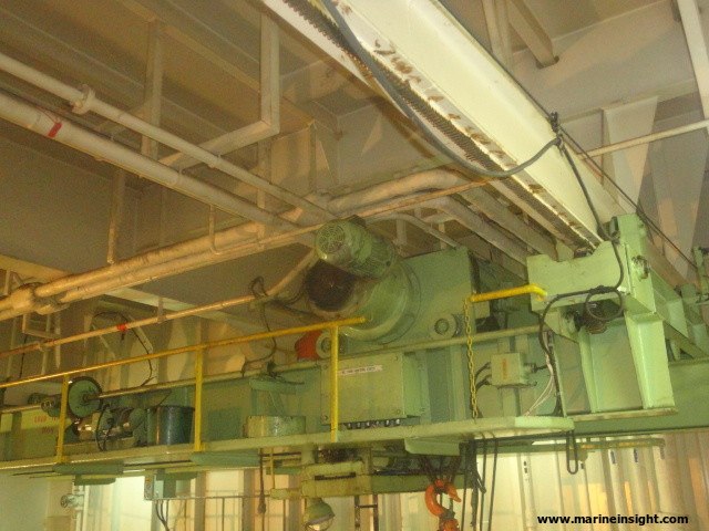
What Are Insulated Shipping Containers?

$
0
0
Container insulation

The trillion-dollar shipping industry transports a wide variety of goods all over the globe. Regardless of whether the goods are meant to be kept hot or cold, dry or wet, packaged or fresh, this industry covers it all.

But transporting so many commodities is not as simple as filling shipping containers with various goods, and then loading them on container vessels.

What do you do if you have to maintain certain products at a sub-zero temperature?

They cannot be transported in the same container alongside items meant to be stored at room temperature. The solution is to transport similar goods in the same container.

And this is where insulated shipping containers come into play.

Without them, it would be near impossible to ship a large variety of items.

In this article, we will go through the various uses, features and types of such containers, that play an integral role in the global shipping industry.

Why do we Need Insulated Shipping Containers?

To understand why a large amount of logistic spending goes on maintaining an insulated and temperature-controlled state for certain goods, let us look at the main products that use this facility.

Pharmaceutical products, fresh produce, beverages, frozen goods, and chemicals often need to be maintained at specific temperatures. They also need to be protected from contamination, by ensuring that air entering and leaving the container is filtered. This is where insulation plays an important role. It completely seals a shipping container off from the outside and helps maintain a fixed condition for the transported goods.

An important point that needs to be understood to comprehend temperature controls on insulated shipping containers is the cold chain. This term refers to a supply chain methodology that keeps certain goods in a permanent cold state throughout its journey from the supplier to the customer.

Insulated shipping container

Image Credit: tpsolutions.eu

By retaining a cold condition, there are no abrupt temperature changes that might cause a variety of problems. For instance, frequent thawing and cooling cycles of food and other produce might cause spoilage.

For pharmaceutical drugs, their composition and reactions might change if the pills or medication are not kept below a certain temperature.

The main idea behind the cold chain is that low temperatures lock in freshness for produce, prevent the growth of bacteria, maintain the required composition of drugs and medicines, help to transport fresh foods, and overall improve the shelf life of foodstuff.

To fully understand why insulation is necessary, let us take an example of a crate of apples coming from the US all the way to India.

While air transport is very useful in such circumstances, it can be difficult for suppliers to transport tons of apples. And so, it is easier to use ships and container vessels for transport.

The journey takes anywhere between 15 to 20 days and requires your package to cross over 15,000 kilometres. Generally, most apples would be spoilt rotten within the first week if they were to make this journey in a normal intermodal container.

However, shipping companies take all efforts to keep the apples fresh and ready for consumption. So, they hire insulated and temperature-controlled containers that have enough space to ship their entire consignment.

This refrigerated container, commonly called a reefer, maintains the apples at a fixed temperature and ensures that there is no external contamination, by fully insulating the container.

When the consignment finally reaches India after more than 2 weeks, it is in a proper state without being spoilt. Further, once the container is unloaded off the vessel and loaded on to the back of trailers, the cold chain must not be broken. So, the same insulated container continues to house the apples until it reaches the customer who transfers it to a cooled warehouse facility.

Throughout this journey, had there not been an insulated container that kept a fixed temperature state, it would have been near impossible to ship apples across the world. And that is why these containers form an important part of the global supply chain and shipping industry.

Although this was a relatively simple example of a crate of apples, the same goes for extremely expensive and essential goods such as pharmaceutical drugs and medicines. In fact, for such commodities, they also filter incoming air in addition to refrigerating the consignment.

Refrigerated Containers

Credits: Andrea Puggioni/wikipedia.org

Since unloading an entire container on to other smaller modes of transport can break a cold chain, most companies prefer to hire a full container, fill it with their goods, and then haul it to their warehouse facilities using trailers.

How to Insulate Shipping Containers

Since the types of goods that are transported on a daily basis are numerous, there must also be a number of ways to ensure that each product reaches its destination in a proper and acceptable condition.

For this, there are a number of methods to create a cool state depending on the condition that they are to be maintained at. Once the cool state has been created, the next problem that arises is regarding how this state is to be maintained. Heat transfer will always occur unless there are proper precautions taken. And this is where insulation comes into the picture.

The first type of container is enclosed in two layers, much like a thermos flask. In between these two layers, there is a vacuum that prevents any transfer of heat between the external conditions and the interior of the container. This method of maintaining the temperature is extremely useful since it requires minimum expenditure.

The only necessity is that some form of coolant is used to lower the temperature initially. Thereafter, the vacuum structure traps in internal energy and prevents it from heating up due to the surroundings.

Another manner in which heat exchange can be prevented is by lining the walls of a container with materials that can easily absorb and dissipate heat. These include liners and thermal blankets, that are generally made of multiple layers. Thermal blankets are large sheets that are usually wrapped around individual pallets, and not around the container. However, liners are structures built into the walls of the container, such that they conserve heat.

A common image that comes to mind when discussing insulating objects is the cooler box commonly found in hot regions. These are boxes or packages that are able to preserve heat by insulating the interior from the surroundings. This is achieved by using materials that are relatively heat resistant and have a tendency to reflect.

Container insulation

Inside of Insulated Reefer Container

Initially, a coolant such as ice or various chemical gels is used to bring the temperature down. To lower the temperature, these materials absorb the heat present within the container and then morph into a different phase. For instance, gels turn into a slightly dense vapour when they are exposed to hot conditions. This is a simple method, that requires the container to be insulated by covering the walls in an appropriate type of material.

The next option to seal in the heat is by using gas-filled chambers, either around the entire container or around individual pallets that fill up the unit. The commonly used gases include inert gases that do not conduct heat and provide a cushion between the surroundings and the interior. Bubble wraps that are used to protect fragile goods can be filled with these types of gases so that they serve the dual function of heat preservation.

The important point to keep in mind while choosing an insulation method is that each type of consignment requires a different implementation. For example, reefers are built to work well with either liners or vacuum panels.

However, produce stored on pallets can use a form of a thermal blanket or inert bubble wrap around them. Depending on the type of goods that you are trying to transport, it is important to consult with an expert to see what is the best option for preserving heat.

Cooling and Other Features in Such Containers

The very principle behind insulated shipping containers is the cooling method used to lower the temperature during the journey.

There are a large number of options available for various types of goods. These range from conventional units like large refrigerators, to chemical agents that change phase to induce lower temperatures.

To induce a cool condition, the easiest method is installing blocks of ice or artificial slurry ice within the container. These blocks lower the temperature, after which insulation materials keep the temperature constant.

Slurry ice is a form of micro-crystal suspended in water that has a decreased freezing point as compared to normal ice. It is easier to use since it has an efficiency of nearly 70% as opposed to 45% for conventional ice. In addition, it can be densely packed which allows for more cooling within the same space constraints.

Reefer unit in container

Reefer unit in insulated container

Other methods of lowering the temperature within a container include dry ice and chemical Phase Changing Material (PCMs). Dry ice is solid carbon dioxide that is well known for artificial cooling. It is commonly used since it does not leave a residue as compared to other types of coolants. It is easily identifiable by thick white smoke that rises as it changes phase. It is toxic in large concentrations, and hence can only be used under certain conditions.

PCMs are substances that absorb heat to lower the temperature and use this heat to change their phase or state. Common PCMs are generally in a solid-state, although they can be liquid as well. As they gradually lower the temperature, they are converted into a gaseous state. Another option is the use of gels that work within specific temperature ranges. Depending on the temperature at which the product is supposed to be stored, various gel packs can be used to absorb heat and lower the temperature.

Along with coolants, several additional features are optionally provided by shipping companies on their containers. These are apt for use on certain types of produce.

For instance, fresh produce can become stale if the same air is circulated within the container for the duration of the journey. Air filters are placed in such containers so that there is some form of circulation. In addition, some types of produce also require a small amount of nitrogen to be pumped into the container, to prevent spoilage.

Nitrogen reacts with any oxygen present in the air and prevents it from causing foodstuff to rot. This nitrogen is introduced in the container using filter systems.

In addition to filters, a necessity on insulated containers such as reefers is a gen-set that provides a backup for power during transit. While on ships, power is provided to keep all refrigeration units functioning. However, since the container must continue the cold chain even during road transport and while waiting at warehouse facilities, gen-sets are provided to power cooling units.

Most containers also use a temperature sensor to constantly monitor heat fluctuations. These sensor readings are to be regularly checked so as to ensure that there is no spoilage. If registered with shipping companies, there are often provisions made to monitor the temperature and provide constant feedback to the company that has hired the container.

Problems and Challenges

As with every good idea, insulated shipping containers also have their own share of issues. Foremost is properly maintaining the cold chain.

No matter the effort is taken during shipment if the chain is broken during transit, whether by road or rail, the goods are unusable and may get spoilt. This is a huge challenge, as it is difficult to always keep a check on the container.

For instance, during transportation of vaccines and medications to sub-Saharan countries during the polio epidemic, a cold chain was maintained until the container was unloaded from the port. From there onwards, it became difficult to power the refrigeration unit, as sufficient supplies of either diesel to run the gen-set were not available, or because electricity was not provided during the journey by road. Thus, by the time the vaccines reached patients, they were either ineffective or toxic.

This created quite the opposite effect of what was intended. Thus, a small break in the cold chain had far-reaching consequences. Even though the medications were within insulated chambers, they were at the mercy of diesel or electricity generation.

In areas with a shortage of resources, it may be difficult to carry on a cold chain for days on end. To aid in this view, several facilities have come up in and around major cities in Africa that allow insulated chambers to function. Also, companies have explored the possibility of using other types of refrigerants instead of reefers in such regions.

The next major problem that affects the insulated container industry is the proper disposal of waste materials, by-products, packaging material, and left-over coolants. Present technology does not allow for recycling packaging material such as gel packs, bubble wraps etc. Hence, they are often simply discarded after their lifetime use, and end up in landfills and incineration sites.

They are immensely harmful to the earth due to the chemicals present within them. Thus, with no other greener alternative, companies are often forced to continue using disposable packaging material. Another major problem is the disposal of coolants. These substances are toxic chemicals that can cause a great deal of damage, as they pollute the air in addition to water bodies. They often include toxic substances such as oxides of poisonous elements and other contaminants.

Trials and experiments into different materials are currently going on, in an effort to reuse or at the least recycle material that will otherwise go to waste. In addition, coolants are also to be handled in a proper manner after their use and disposed of in certified containers.

Some coolants can be released back into the air, or integrate into water bodies without harming the natural ecology. However, the vast majority need to be destroyed and incinerated. For this, dedicated facilities that carry out incineration in a proper manner are required.

To Conclude…

The shipping industry is a modern marvel that allows almost every type of commodity to be shipped thousands of kilometres around the globe. This would not be possible without insulated containers, that keep items fresh and safe.

From fresh produce, meats, medicines to pharmaceutical drugs, a variety of conditions are met to allow for long-distance shipment.

For logistics and supply chain specialists, it is important to recognize that different goods require different techniques to remain fresh and usable. Identifying the correct method, and inspecting insulated containers are the first steps in ensuring quality control.

Some of the factors to take into account include the temperature sensitivity of the goods, the changes it undergoes when exposed to a low temperature for prolonged periods, and the size of each individual pallet or crate that is used.

A large number of shipping companies offer multiple types of insulated containers. When choosing the right choice for you, look for important qualities such as in-built refrigeration systems, warranty and quality checks, filter systems, quality of insulation seals around the edges of the container, standardization certificates etc.

If properly assessed, these insulated shipping containers can be a huge asset for companies and will allow them to ship a wider variety of goods.

Disclaimer: The authors’ views expressed in this article do not necessarily reflect the views of Marine Insight. Data and charts, if used, in the article have been sourced from available information and have not been authenticated by any statutory authority. The author and Marine Insight do not claim it to be accurate nor accept any responsibility for the same. The views constitute only the opinions and do not constitute any guidelines or recommendation on any course of action to be followed by the reader.

The article or images cannot be reproduced, copied, shared or used in any form without the permission of the author and Marine Insight.

Compressed Air Line On Ships – A General Overview

$
0
0

Compressed air on ships is used for different purposes. High-pressure air of 30 bar is mainly used for the main engine starting.

This high-pressure air is reduced to lower working pressures through pressure reduction valves and is used for other important purposes.

The air at reduced pressures of 7-8 bar is used as service air for a number of applications.

Some of these include starting of Auxiliary Engines, Emergency Generators, Charging of freshwater and drinking water hydrophores, blowing the fog horn, spring air for exhaust valves of the Main Engine, dry washing of Main Engine turbochargers, for use in sewage treatment plants for aerobic sewage breakdowns, soot blowing of boilers, pneumatic pumps for oil transfers and many more applications such as service air for the use of cleaning, painting operations, chipping and operation of pneumatic tools such as grinders, chisels etc.

One more important branch of this 7-8 bar compressed air is used as control air. The control air is a filtered branch of the service air which is made free of any moisture and oil carry-over. This controlled air is used for pneumatic controllers and is important for the operation of machinery onboard ships.

This makes the air line on a ship a very important aspect of ship operations. This article throws light on the air line of a Ship in general, its important components and working.

The complete pneumatic air line on a ship includes the Main High-pressure airline, the service air line and the control air line.

Main Air Compressor

The main air compressor is the heart of the air-line onboard. The air compressor compresses air by means of reducing its volume so as to raise its pressure. Air compressors can be of various types. They include

1. Centrifugal Compressors
2. Rotary vane compressor
3. Rotary screw compressors
4. Reciprocating Air compressors

Most modern merchant vessels are employed with multi-stage reciprocating air compressors having intercoolers & aftercoolers with auto-draining and unloading arrangements.

The capacity of the main air compressor is expressed in terms of Free Air Delivery (FAD) and is stated in cubic mtrs /hour.

Free Air Delivery can be defined as the volume of air actually discharged by the compressor in 1 hour, that would occupy if expanded down to atmospheric pressure and cooled to atmospheric temperature.

The discharge of the main air compressor is led into a main air bottle or reservoir which stores this pressurised air at a maximum of 30-32 bar.

A ship may have 2 or 3 main air compressors depending upon many factors such as each air compressor capacity, amount of volume of air needed for starting of the Main Engine, demand of air on that particular ship etc.

The marine boilers and exhaust gas economizers on certain ships are soot blown with air, these ships may be employed with higher capacity air compressors at the design stage depending on ship owners.

As per SOLAS requirements, a ship’s main air compressors should be able to fill its air reservoirs from 0 to maximum pressure (30bar) within 1 hour.

Main Air Reservoir

Each ship is equipped with a set of 2 air reservoirs. They may be of the vertical or horizontal type.

Air reservoirs are hydraulically pressure tested to 1.5 times its working pressure.

As Per Solas Regulations –

The total capacity of air reservoirs must be sufficient to give at least 12 consecutive Main Engine starts for a reversible engine, and at least 6 consecutive starts for a non-reversible engine without refilling of the reservoirs.

There must be 2 identical main air receivers and 1 emergency air bottle for every vessel.

Air Reservoir Mountings

Each air reservoir should be equipped with the following mountings:

1. Fusible Plug

Composition – Bismuth 50%, Tin 30%, Lead 20%
Melting Point: 220deg F (104.4deg cel) Fitted at the reservoir’s bottom or on the reservoir at the ship side when a relief valve (safety valve) is not directly fitted on the reservoir.
It is fitted to release the compressed air in the event of abnormally high compressed air temperature.

2. Atmospheric Relief Valve

It is provided as over-pressure protection and as a back-up of the fusible plug.

In case of an Engine Room fire when CO2 flooding is required, this valve is to be opened before evacuating the engine room.

(The air receiver relief valve opening could either open outside the engine room through the ship’s funnel or inside the engine room itself. In case of the latter, CO2 bottle calculations for fighting a fire in the Engine room is done accordingly and the extra CO2 required is taken into consideration at the ship’s design stage)

3. Spring Loaded Safety Valve

Setting pressure 32 bar (for a 30-bar working pressure) with equal to or greater than 10% rise in accumulation of pressure may be fitted directly or with extension.

4. Compensation Ring

When a hole is cut or machined into a pressure vessel, higher stresses will subject to the material around the hole, and to reduce this, compensation rings are fitted.

It is a flange on which a valve or fitting is usually mounted. A compensation ring provides for structural integrity in the air pressure vessel.

5. Manual Drain valve or Automatic Drain valve

6. Pressure gauges

7. Access doors

8. Main Starting valve, auxiliary starting air valve, fitting valve, service air or whistle air valve

Large cylindrical air bottles usually have one longitudinal welding seam. The longitudinal and circumferential seam is machine welded with full penetration welds.

The welding details are governed by the pressure of air that is to be stored in conjunction with classification society regulations.

All welded air receivers have to be stress relieved or annealed at a temperature of about 600 deg Celsius and the welding is to be radiographed for safety purposes.

Receivers are subjected to statutory survey and inspection, periodically hydraulic tested at 1.5 times the working pressure, is to be applied every 10 years for large receivers.

SUCCESSFUL MARINE ENGINEER ebook

Air Bottle Inspection

Air receivers are to be inspected as per PMS and checked for any signs for corrosion. Moisture in air receivers can give rise to corrosion and despite the proper operation of compressor cooler drains, a large amount tends to collect, particularly in humid conditions.

It is good practice to check air reservoir drains regularly to assess the quantity of liquid present. In extreme conditions, drains may have to be used 2-3 times daily to remove accumulated emulsion. Mostly corrosion is found near the air receiver drain.

After thorough visual inspection, if required, thickness measurement can be done using an ultra-sonic thickness gauge. If the thickness of the air receiver is compromised, we have to reduce the air pressure to be contained in that particular air bottle.

Air Bottle

Starting Air Bottles

This, after certain calculations, can be done by changing the cut-in, cut-off settings of the air compressor when that particular receiver is in use and relief valve settings have to be re-adjusted. Also, the air receiver can be isolated completely and kept on stand-by, can be filled manually with caution, whenever required.

All internal welds or small changes in cross-section need to be thoroughly inspected.

If the air bottle is too small to manually enter, then internal inspection can be carried out using a camera with a probe.

Internal Surface Coating

Should be graphite suspension in water, Linseed oil, Copal Vanish or Epoxy coating, having basic properties such as anti-corrosive, anti-toxic and anti-oxidation.

Safety Devices On Main Air Bottle

1. Fusible Plug
2. Pressure relief valve
3. Atmospheric Relief Valve
4. Low-Pressure Alarm
5. Automatic or Remote-control moisture drain valve

The Control Air System

A branched airline through a pressure reducing valve is supplied to the Control Air line.

Pneumatic control equipment is sensitive to contaminants which may be in compressed air. Viscous oil and water emulsions can cause moving parts in control equipment and control valves to stick and produce general deterioration of diaphragms, spools and other parts made of rubber.

Water can cause rust build-up which may also result in parts sticking or being damaged by these rust particles. Metallic wear and other small particles can cause damage by abrasion.

Any solids mixed with oil and water emulsions can conspire to block small orifices. Clean and dry control air is thus essential for the trouble-free operation of control- air systems.

When the source of control and instrument air is the main air compressors and the main air reservoir itself, then special provision is necessary to ensure that air quality is high.

The pressure reducing valve which brings the main air pressure to the 7 or 8 bar required by the control air system, can be affected by emulsion carry over and can require frequent cleaning to stop air contamination.

Automatic drain traps may be fitted in the control air system, but many have traps which require daily draining by the engine crew.

Large amounts of free moisture and oil emulsion carry-over in the air can be removed by special control-air membrane filters installed in the control air line.

Control Air Filter

A typical control air filter arrangement consists of an oil & moisture collecting filter followed by a membrane air dryer filter. The treatment of air through these membrane filters results in the air being filtered and dried in order to remove virtually all traces of oil, moisture and air impurities.

A simple line air filter is provided with a small plastic float and auto drain arrangement.

The filter can also be drained manually if the vessel enters a highly humid environment and frequent draining is required.

The filter dryer unit is made up of a primary filter, secondary filter and membrane hollow fibre elements.

Air Flow Through The Control Air Dryer

The control air enters the dryer chamber through the line filter located in the lower part of the dryer unit. In the dryer unit, the primary filter removes the coarse rust particles, dust and other larger impurities.

The secondary filter acts like a coalescer, separating water droplets and oil mists up to 0.3 microns. A differential pressure gauge indicates the condition of the primary and secondary filters.

A higher differential pressure indicates a dirty membrane filter. The membrane elements are to be renewed as per the ship’s PMS.

Piping

The high-pressure air piping from the air compressor to the receiver should be as smooth as possible without any bends in the pipeline so as to allow air to flow freely to the receiver without restrictions. Bends in the piping can create backpressure in the line in case of accumulated moisture or oil emulsion in the line.

Emergency Air Compressor And Emergency Air Bottle

The emergency air compressor is a small independent air compressor which can be either driven by an independent prime mover like an engine or having a power supply from the emergency switchboard.

It is used to fill up the emergency air bottle which has a sufficient volume of air to start the auxiliary engine of a dead ship.

The control air onboard is also used in the Emergency Shut-Off Valve operating system.

An emergency QCV – Air bottle with 7 bar air pressure is used to operate all Quick Closing valves, fire and funnel dampers on board.

This arrangement consists of a 7 bar Emergency QCV air bottle with QCV- shut off valves that are to be always in a state of readiness.

In case of an uncontrollable fire in the engine room, the Quick closing valves are operated which supply this control air to SHUT specific outlet valves of all Fuel Oil and Lube Oil tanks and ER funnel and Blower dampers thereby cutting off all fuel and air supply.

Control Air Supply is also used on Emergency Shut Down Systems (ESDS) on Gas Tankers.

Disclaimer: The authors’ views expressed in this article do not necessarily reflect the views of Marine Insight. Data and charts, if used, in the article have been sourced from available information and have not been authenticated by any statutory authority. The author and Marine Insight do not claim it to be accurate nor accept any responsibility for the same. The views constitute only the opinions and do not constitute any guidelines or recommendation on any course of action to be followed by the reader.

The article or images cannot be reproduced, copied, shared or used in any form without the permission of the author and Marine Insight.

Selective Catalytic Reduction (SCR) Reactors For Ships – Types, Working Principle, Advantages And Disadvantages

$
0
0

What is NOx and where does it come from??

NOx pollution occurs when nitrogen oxides are released as a gas into the atmosphere during the high-temperature combustion of fossil fuels.

These nitrogen oxides consist mainly of two molecules, nitric oxide (NO) and nitrogen dioxide (NO2) along with a few others that occur in much lower concentrations. These molecules- Nitrous oxides are a significant greenhouse gas that plays an important role in Global Climate Change.

Nitrogen oxides form when oxygen and nitrogen from the air interact during a high-temperature combustion event. These conditions occur in Internal Combustion Engines and fossil fuel-powered electricity plants.

Environmental and Health Concerns

NOx gases play an important role in the formation of smog. When exposed to the UV rays in sunlight, NOx molecules break apart and form ozone (O3). The problem is made worse by the presence of volatile organic compounds (VOC) in the atmosphere, which also interacts with NOx to form dangerous molecules. Ozone at the ground level is a serious pollutant, unlike the protective ozone layer much higher up in the stratosphere.

In the presence of rain, nitrogen oxides form nitric acid, contributing to the problem of acid rain.

Nitrogen oxides, nitric acid, and ozone can all readily enter the lungs, where they create serious damage to delicate lung tissue. Even short-term exposure can irritate the lungs of healthy people.

For those with medical conditions like asthma, just a short time spent breathing these pollutants have proved to be fatal. This air pollution can lead to respiratory diseases such as emphysema and bronchitis. NOx pollution can also worsen asthma and heart disease and is associated with elevated risks of premature death.

The International Shipping Industry is facing an increasingly tight regulatory environment, especially in terms of limits imposed upon emissions to air. And with the entry into force of the International Marine Organization’s (IMO) NOx Tier III limits on January 1st 2016, a part of MARPOL Annex VI, the regulations governing marine emissions became significantly tougher and stringent to follow.

As per MARPOL Annex VI, Regulation 13- Nitrogen Oxides (NOx), the Nitrogen oxides from diesel engines on board are to be controlled as follows

The NOx emission limits are set for diesel engines depending on the engine maximum operating speed (rpm), as shown in the above table, Tier I and Tier II limits are global, while the Tier III standards apply only in NOx Emission Control Areas.

There are two exceptions – engines used solely for emergencies and engines on ships operating solely within the waters of the state in which they are flagged. The latter exception only applies if these engines are subject to an alternative NOx control measure.

Emission Control Areas must comply with NOx “Tier III” emission limits which means that they must emit 80% less nitrous oxides than a “Tier I” complaint engine. Under these regulations, ships which are keel-laid after January 1st 2016 and operating in the United States/Canadian Emission Control Areas(ECAs) must comply with the new emission limits.
These emission limits are applicable for engines with an output power of more than 130kW installed on ships with more than 5,000GT

Tier III standards are expected to require dedicated NOx emission control technologies. These mainly consist of two options.

1) Using Liquified Natural Gas (LNG) as a fuel in engines, using lean burn technology.
e.g.- Win GD Engines-Winterthur Gas & Diesel Ltd. which burn LNG in their combustion chambers using a Low-Pressure LNG gas injection system for the reduction in NOx emissions.

2) Use of abatement technology such as various forms of water induction into the combustion process (with fuel, scavenging air(in-take air humidification), or in-cylinder), exhaust gas recirculation, or selective catalytic reduction.

This article throws light upon Selective Catalytic Reduction Reactors on Ships, it’s types, their basic working principle, components, its benefits, advantages and disadvantages.

Basic Working Principle 

Selective Catalytic Reduction is a means of converting nitrous oxides in the exhaust with the help of a catalyst into diatomic nitrogen and water.

A reductant Anhydrous Ammonia (NH3), Aqueous Ammonia (Ammonium Hydroxide) or Urea (Carbamide) solution is added to a stream of exhaust gas and is adsorbed onto a catalyst. Carbon Dioxide (CO2) is a reaction product when urea is used as the reductant.

The chemical equation for the reaction using either anhydrous aqueous ammonia for the process is

4NO + 4NH3 + O2 = 4N2 + 6H2O
2NO2 + 4NH3 + O2 = 3N2 + 6H2O
NO + NO2 + 2NH3 = 2N2 + 3H2O

The reaction for urea instead of anhydrous or aqueous ammonia is
4NO + 2(NH2)2CO + O2 = 4N2 + 4H2O + 2CO2 (in presence of catalyst)

Selective Catalytic Reduction

This exhaust gas after-treatment technology has a NOx abatement capability Of more than 80%. The SCR concept involves injecting a Urea-Water solution into the exhaust gas stream in combination with a special catalyst unit.

The SCR is considered as an additional and independent exhaust treatment system and as such does not interfere with the basic engine design or combustion process.

The process diagram below gives a better understanding of the SCR system wherein the urea interacts with nitrous oxides present in the incoming exhaust gas, in the presence of a catalyst, converting it into free nitrogen and water vapour.

The Maritime Environmental Protection Committee (MEPC) At The IMO has published guidelines for the certification of selective catalytic reduction (SCR) systems, referred to the “SCR Guideline”, namely IMO Resolution MEPC.198(62).

According to their configurations, SCRs can Be Classified into 2 Types- They can be either installed between The Exhaust Gas Manifold & The Turbocharger or between The Turbocharger and The Exhaust Gas Boiler.

1) High-Pressure SCR 

In the High-Pressure SCR, the reactor is placed before the turbocharger. A sufficient exhaust

gas temperature is to be maintained between 300 to 400 deg Celsius, which might be challenging when the engine is running at low loads and manoeuvring.

Therefore, for two-stroke engines, the most likely location of the SCR unit is before the turbocharger in order to expand the active range of SCR operation. This has little to no effect on the engine combustion process.

It is possible to run high-pressure SCRs on Heavy Fuel Oil.

2) Low-Pressure SCR

In Low-Pressure SCRs, the reactor is placed after the turbine. Pre-heating of the exhaust gas stream may be necessary in order to achieve a sufficient temperature at the reactor inlet for the catalytic reaction. Some power generation may be needed for preheating.

Components of an SCR 

Dosing Unit

The dosing unit consists of a compact external dosing system having a urea-water solution tank. The tank size depends upon how often the vessel enters NOx Tier III areas and how often the SCR is put in use. Urea Tank capacities range from 4 to 10 cub metres/MW for larger engines.

The area for marine use is usually dissolved in water having a concentration of 32%-40%. Urea is a non-toxic odourless solution considered safe to transport and store at ambient temperature & pressure. However special caution is required in winter temperatures in order to avoid crystallization.

The dosing handling system provides the reducing agent (urea solution) based on the dosing demand signal provided by the SCR and Engine control and monitoring system.

Vaporizer/ Mixing Unit

The urea from the dosing system is metered and injected into the vaporizer or mixing unit. The injected reducing agent (urea) will vaporise and mix with the incoming exhaust gas.

The mixing unit is in line with the exhaust manifold of the engine and its pipes are designed & constructed after complex flow calculations & intensive testing, to ensure a good mixture of the urea solution & hot exhaust gases. The mixing unit is usually 2 to 6 meters long and 500mm in diameter, however, size may vary as per Engine size.

Injection tubes from the dosing unit penetrate the vaporizer from the bottom, the top of the vaporizer is equipped with an electronic enclosure having a NOx measurement sensor to monitor nitrous oxides in the exhaust gas and Backpressure sensor.

SCR Reactor Chamber

This is where the conversion of NOx in exhaust gas into nitrogen and water takes place in the presence of catalyst material. The SCR reactor contains cassettes of the catalyst substrate material. The substrate elements work in limited temperatures, if exhaust gas temperature is too high, the elements get destroyed.

If the temperature is too low, SCR efficiency is reduced. Catalyst element contains Vanadium Pentoxide (V2O5) which helps the reaction process of converting the urea and exhaust gas into nitrogen and water vapour. The SCR reactor volume is usually 1.5-3 cub metres/MW installed power.

Fuel Oil Quality and SCR technology

The sulphur content in fuel oil and consequent SO2 concentration in the exhaust gas is a critical parameter which has to be observed while operating SCR systems. Urea temperature is to be controlled according to sulphur content in fuel.

A high sulphur content in presence of a low exhaust gas temperature (in case of manoeuvring) will require a higher temperature of urea solution to be injected as a condensation of exhaust gas could result in corrosion and catalyst substrate damage. A lesser content of sulphur in fuel will allow a lesser temperature of urea solution to be injected.

Condensation of water vapour in the presence of sulphur in the exhaust gas during low load operations can cause the formation of solid ammonium bisulphate. Thus, the exhaust inlet temperature is to be kept high enough to avoid condensation of ammonium bisulphate onto catalyst substrate elements.

Condensation would severely affect NOx reduction performance and cause clogging, increasing backpressure due to soot formation in the reactor.

Soot Blowing Unit

To prevent contamination of the reactor elements, a soot blowing system is installed. Soot blowing is done using compressed air of 7 bar.

SCR Control Sensor Unit

NOx sensors measure the NOx concentration before the SCR reactor and the turbocharger.
The reactor chamber also contains outlet NOx sensors and outlet temperature sensors.

Venting System

The venting system vents the SCR reactor when the SCR is bypassed (i.e. when the engine is running in Tier-II mode) to avoid exhaust gas accumulation and soot formation in the reactor. The reactor is vented with Fresh Air during Tier II operation.

The Reactor Sealing Valve is used to seal the reactor during venting when the SCR is not in use.

Reactor Throttling Valve is located at the outlet of the reactor.

Reactor Bypass Valve is used to bypass the reactor for NOx Tier II operation or failure of the SCR.

The Cylinder Bypass Valve can be used while the engine runs at partial loads to bypass scavenge air towards the turbocharger to increase exhaust gas temperature.

The Cut-In Cut-Out settings of Auxiliary blowers are set slightly differently in case of engines fitted with SCRs. While cutting-in of auxiliary blowers at the time of reducing load, a slight delay is introduced so as to avoid a sudden drop in exhaust temperature.

Similarly, while cutting-out the auxiliary blowers, when engine load increases, the exhaust temperature tends to increase suddenly, to prevent this- the Cylinder Bypass Valve (CBV) opens first to gradually increase temperature, then the blowers cut out and the CBV later closes as per engine load.

Pros & Cons Of The SCR

To assure continuous NOx removal and avoid clogging, special considerations have to be observed with regard to exhaust temperatures.

Pros

● Tier III NOx compliance is achievable.
● Very efficient NOx removal for most engine loads (60-90%)
● SCRs have a widely growing reference base with over 300 installations

Cons

● Rather investment intensive
● Limited NOx removal at low engine loads
● In comparison to other solutions for NOx Tier III emissions, the use of urea requires the installation of urea tanks which may have to be replenished often (a costly affair)
● Can result in excess consumption of fuel (about 1%)
● Additional cost of Urea in ECA areas.

Maintenance

● Replacing NOx sensors- sensor life is approx. 2000hours
● Replacing the substrate catalyst elements in the SCR reactor (Lifetime-approx. 1000hours)
The lifetime of the catalyst elements strongly depends upon the sulphur content of the fuel. For NOx Tier III compliance, NOx efficiency is to verified once a year.
If NOx efficiency reduction < 70% all catalyst elements must be renewed as per manufacturer’s instructions.
● The Soot Blower consists of a compressed air bottle, soot blower diaphragm valves and pressure switches. All pressure hoses are to be checked and diaphragm valves to be maintained.
● The Dosing Unit consists of a urea solution tank, liquid filters, dosing pumps, nozzle assemblies, flowmeters, valves and pressure switches.
Weekly maintenance includes cleaning of filters, monthly includes inspection of injectors. Proper inspection and working of all individual components are to be checked every 6 months.

Benefits For The Ship Owner/Operator

Installing NOx Tier III-compliant technology has been beneficial beyond just achieving compliance with emissions regulations. Demonstrating a company’s commitment to ensuring sustainable operations has become increasingly important.
Some additional advantages include direct financial benefits, as major ports offer substantial discounts in harbour fees. One frequently used performance indicator for the environmental impact of shipping is the Environmental Shipping Index (ESI), which is used by major ports to calculate harbour fees.
Installing Tier III-compliant technology, instead of Tier II-compliant technology, adds approximately five points on the ESI scale.

For example, the following reductions in harbour fees for operating on Tier III are given by these ports:

Los Angeles: $2,500 per call (ESI higher than 50)
Hamburg: €1,500 per call (ESI higher than 50)
Rotterdam: 20% reduction for Tier III
Antwerp: 10% ESI higher than 31

Image credit: Cat Marine

Disclaimer: The authors’ views expressed in this article do not necessarily reflect the views of Marine Insight. Data and charts, if used, in the article have been sourced from available information and have not been authenticated by any statutory authority. The author and Marine Insight do not claim it to be accurate nor accept any responsibility for the same. The views constitute only the opinions and do not constitute any guidelines or recommendation on any course of action to be followed by the reader.

The article or images cannot be reproduced, copied, shared or used in any form without the permission of the author and Marine Insight.

Viewing all 277 articles
Browse latest View live